— 15 —
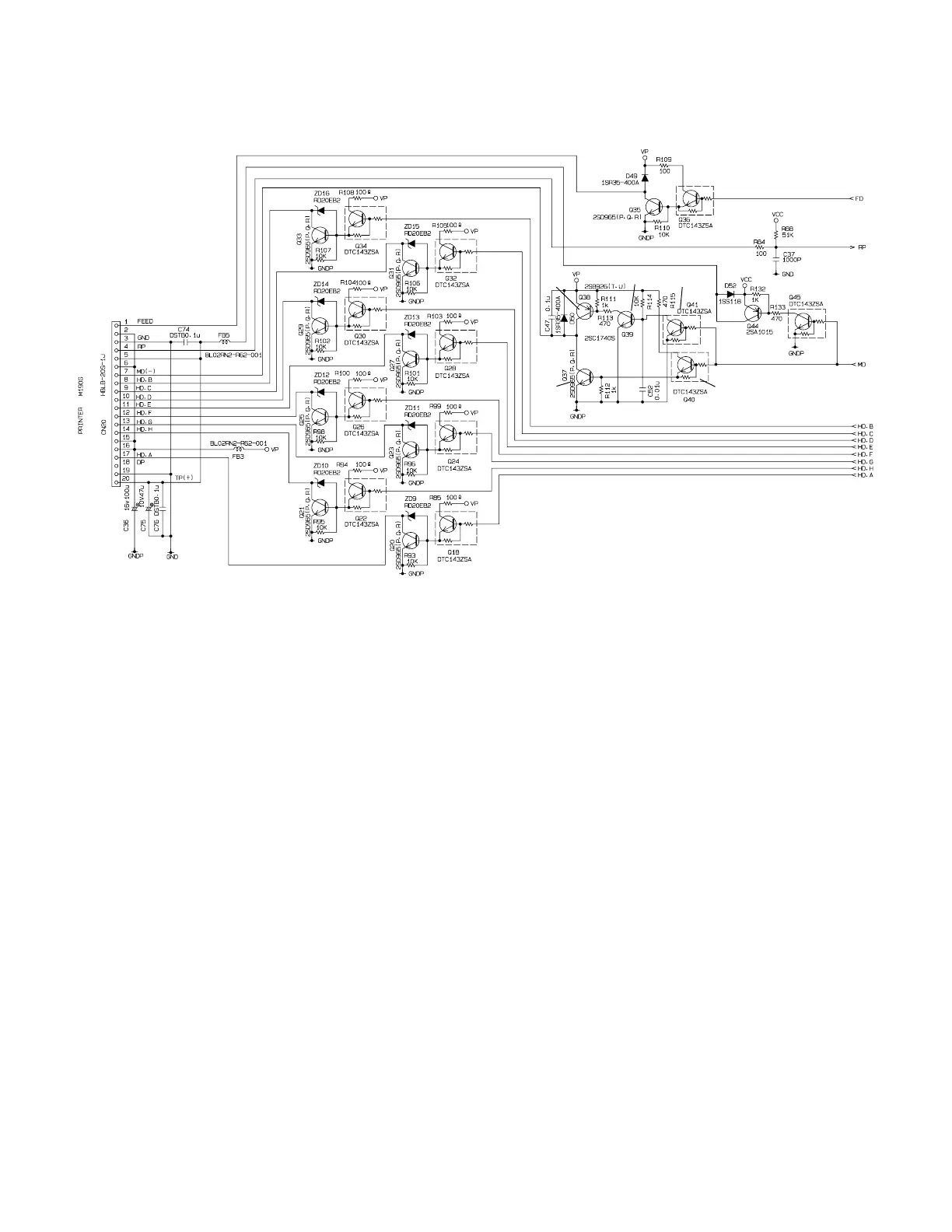
6-9. Head drive circuit for printer
Motor drive circuit
Normally, the transistor of motor drive circuit is followng condition.
TR1,TR2,TR5 : OFF
TR3, TR4 : ON
MD(-) signal : VP level
When the CPU want to rotate the motor, CPU change the MD signal to "High" from "Low".
Then, TR1,TR2 and TR5 are become ON and MD(-) signal is become GND level,
and then motor is rotated.
Head drive circuit
When the CPU wants to print, CPU send "High" signal from HD.A ~ HD.H terminal.
This signal goes to printer unit, and then print.
RP : Reset pulse from printer
DP : Dot pulse from printer
TR1
TR2
TR4
TR3
TR5