— 16 —
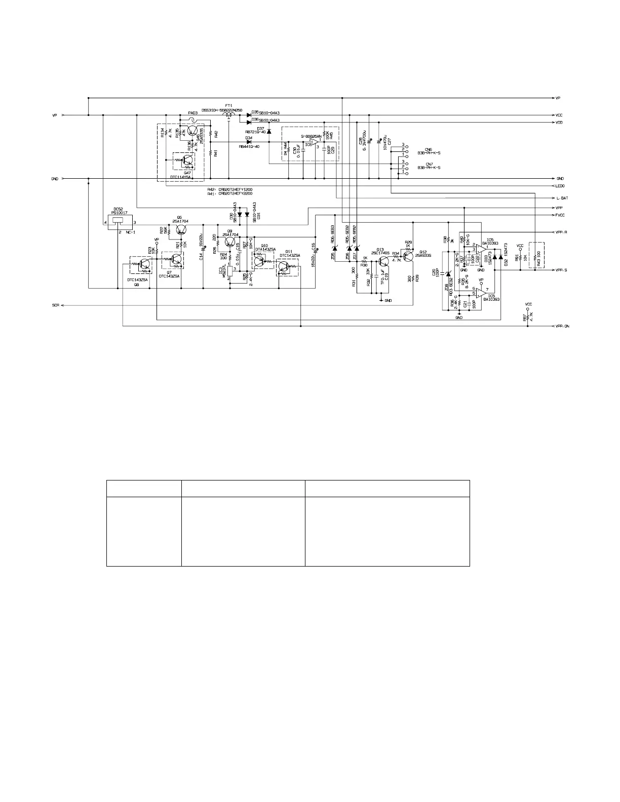
6-10. VPP sensor circuit
Normal To write the data to Fiscal ROM
VDD +5.1V +5.1V
VCC +5.1V +5.1V
FVCC +5.4V +6.5V
VPP +5.2V +13.1V
VPP.S Previous condition Inverted ( *1)
Note *1 : When the "VPP" became 13.1V, "VPP.S" level is inverted.
This circuit is using for making the voltage when the CPU write the data to Fiscal ROM.
When the CPU wants to write the data to Fiscal ROM, CPU makes the "VPP.ON" signal
to "Low level".
DCS2 (PS10017): Booster circuit ( from 5V to 13V )
IC3 (M5237L) : IC for making 5V from 13V
Each voltage level (Unit : V)