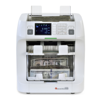
CassidaPRO Zeus: Service Manual
2018 Cassida Corporation. All rights reserved.
Rev: 09/05/2018
cassidapro.com/partner/
abnormal spikes which indicate issues with the CIS bar. Each
color’s graph should mimic the others regardless of shape. The IR
illumination graph should be similar, but of lower amplitude.
• IRT and UVT - This image displays the scanning quality of the
IR and UV sensors. In general, the IR waveform should be ‘U’
shaped with a relatively flat bottom. The UV waveform (BRIGHT
BLUE) should be relatively flat. Both waveforms should be free of
spikes or 0 values between the vertical bounding lines.
[6] CPU S/N
• This menu provides the unit’s CPU IDs (CPU0 and CPU1) and
detailed information about the unit. This information is stored on the
main board of the unit. Cassida may request this information if the
technician or end user needs to unlock the Zeus for extra software
features.
[7] Sensor Detail
• This menu option provides a simple and fast way to troubleshoot the
hardware in the Zeus. This is the first menu suggested to diagnose
possible hardware issues, which allows the technician to exercise most
components of the unit. By pressing the marked number numbers on
the display, the technician can test each component independently.
For every component that passes the default range tests built into the
software, the menu option will turn BLUE. If a sensor fails, or is out of
range, the value will turn RED.
1. Main Motor Forward
2. Main Motor STOP
3. Main Motor Reverse
4. Toggle Selector Position to Reject Pocket
5. Toggle Selector Position to the Stacker
6. Unused
7. Toggle Wing Motor On/Off
8. Toggle Power Supply Fan
9. Close Dust Cover
The technician may then check the remainder of the sensors by:
• Opening Upper Door/Opening Lower Door
• Verify 2000 < Double Level < 3000
• Cover Hopper Sensor
• Cover Reject Pocket Sensor
• Cover Stacker Senor
[8] Keypad Test
• This menu allows the technician to verify that all buttons on the front
panel of the unit are functioning correctly. In order to exit this menu,
the user must press EVERY button on the front panel and ensure it has
been selected. Use this to diagnose issues with the keypad, [C], or
[START/STOP] keys.
DIAGNOSIS 6.2.

 Loading...