5.9 Router Stop Switch (NC) 21.22
The Router Stop Switch consists of a magnetic reed switch (with wires) and a magnet (no wires).
It is Normally CLOSED (NC) and OPENS at the end of the pocket routing stroke when the Motor
Carriage breaks the magnetic field. The switch signals two solenoid valves that reverse the
direction of airflow in the drive cylinder
causing the carriage to retract the Router and extend the
Pilot Hole Drill.
If the switch fails, or the magnetic field weakens or becomes misaligned, the machine will not
sense the end of the rout cycle properly and the router may stay forward in the pocket causing
the cycle to stall, or the router may not extend at all although the Pilot Hole Drill and Clamp finish
the cycle.
5.9.1 TROUBLESHOOING STEPS:
1. Disconnect power and air from the machine. Open rear access door.
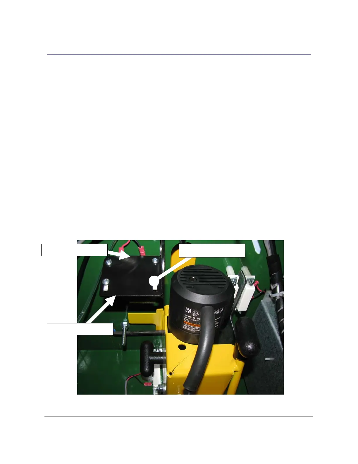
2. The Router Stop Switch and Magnet are attached to the back side of the Router Stop
Plate, which is located just to the left of the Drill motor. See Fig 10.
Router Stop Switch Router Stop Plate
Router Stop Magnet
Fig 10
TSM-21 Diagnostic Manual Parker/Humphrey Solenoids