6.
Push the carriage forward by hand. The carriage should “spring” back when released.
7. Reinstall the Control Box and reconnect air and then power to the machine.
5.16 Drill Stop Switch (NC) 21.43
The Drill Stop Switch consists of a magnetic reed switch (with wires) and a magnet (no wires).
The switch is Normally CLOSED (NC) and OPENS at the end of the Pilot Hole cycle when the
Motor Carriage breaks the magnetic field. The switch then signals both the Drill solenoid and
Clamp solenoid to stop airflow, which allows the Drill to retract and Clamp to release.
If the Drill Stop Switch fails, or the magnetic field weakens or becomes misaligned, the machine
will not sense the end of the drill cycle. The drill may stay forward in the Pilot Hole causing the
cycle to stall or the clamp may extend but immediately release.
5.16.1 TESTING STEPS:
1. Disconnect power and air from the machine.
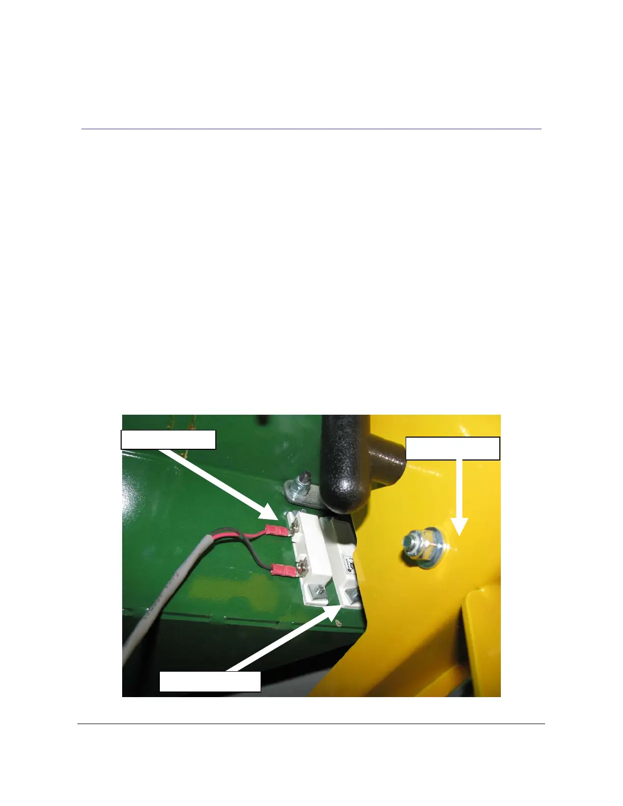
2. The Drill Stop Switch and magnet are located inside the machine on the back side of the
Face Plate, slightly to the left of the Pilot Drill Hole. See Fig 17.
Drill Sto
Switch
Motor Carriage
Drill Stop Magnet
Fig 17
NOTE:: If the bar spring is out of position and on the wrong side of the carriage bolt, then router bit
will be above the work surface and the drill bit will not extend when running a cycle. Reposition the
bar spring to the correct position in Fig 17 to correct.
TSM-21 Diagnostic Manual Parker/Humphrey Solenoids