5.2 MSD Configuration
Your MSD has been manufactured to operate in a specific RF band and is fitted with a specific Ethernet option.
● Within that band all users can configure the specific RF channel.
● Authorized users can set the System master address.
● Ethernet options are None, EtherNet/IP or PROFINET
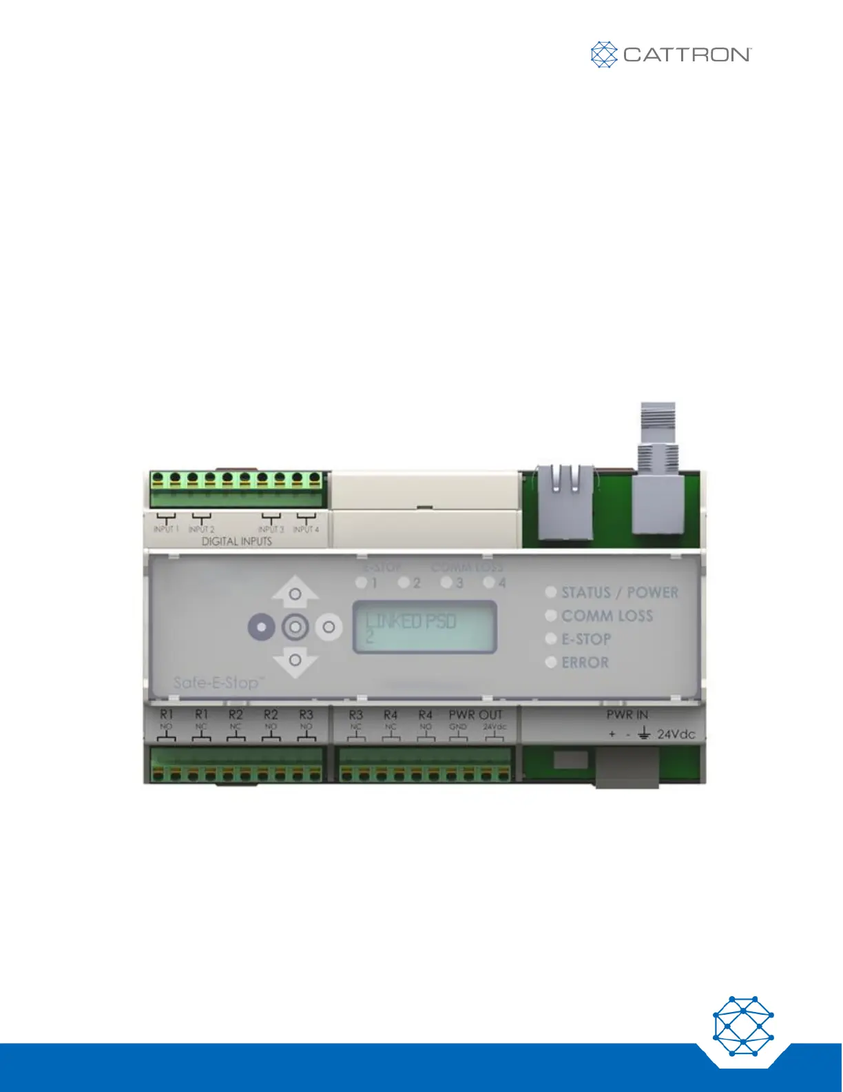
Each MSD’s configuration is identified on the unit’s LCD screen.
A system of one MSD and one or more PSDs must have a correct set of configuration parameters to be able to
operate. Most of the configuration details must match exactly; only the Sub-Address must be different between
PSDs.
In summary:
▪ A PSD and MSD have one matching Master Address and each PSD has a different Sub-Address.
▪ Both PSDs and MSD have one unique frequency and master address.
Figure 2: MSD
The MSD will show its configuration on the LCD when first turned on. The configuration can also be displayed by
scrolling down using the selection arrows.