This will be flashing:
GREEN: Normal operation
ORANGE: Conditions that require the user to be aware
RED: Conditions that require the user to take corrective action
6.2.1.1 PSD LCD
The LCD provides valuable information to the user. A backlight turns on each time there is a change of displayed
message and the backlight will remain on for 10 seconds.
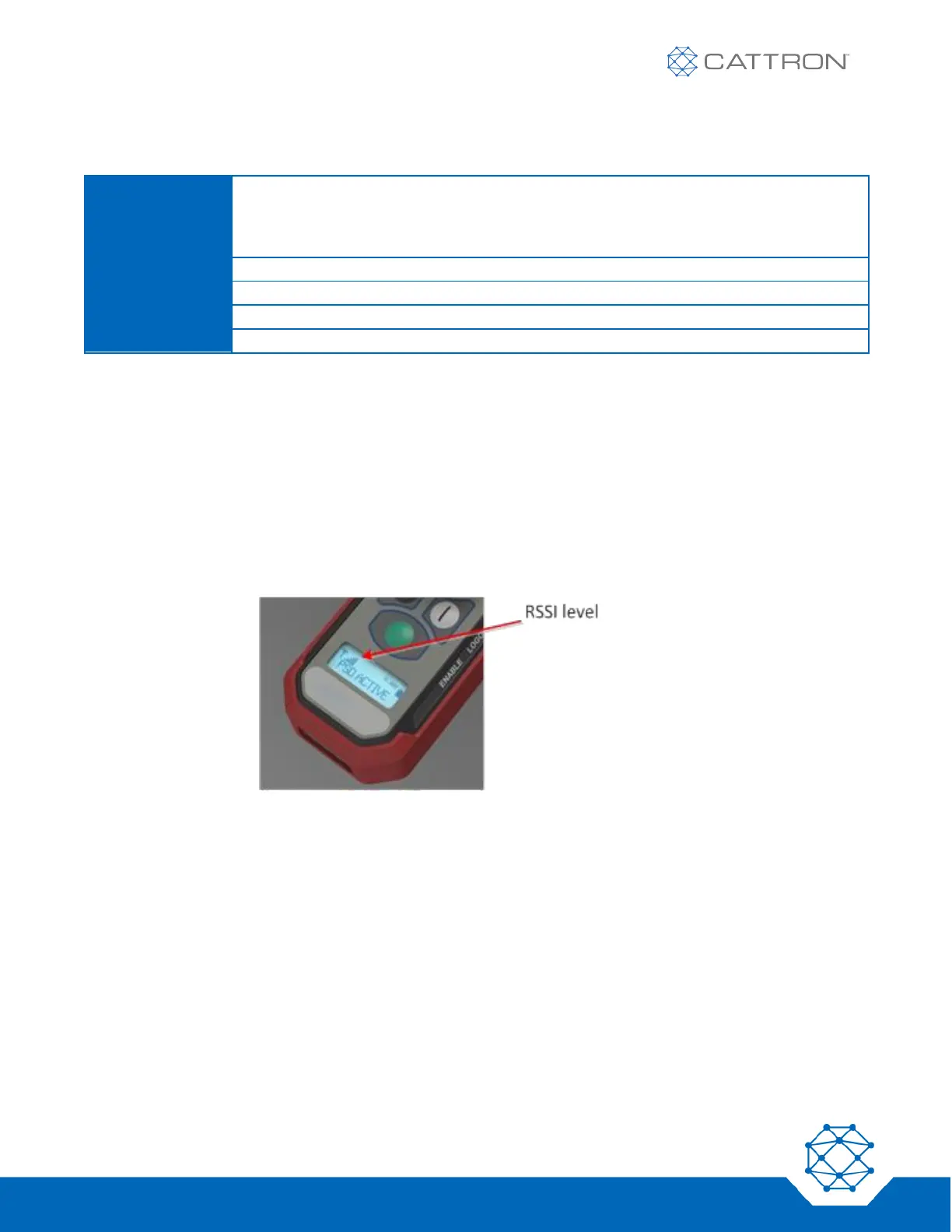
6.2.1.2 Radio signal level Monitoring
The RF signal level is displayed on the PSD using a graphic icon, as shown in Figure 4.
More bars mean more signal. Very low signal will be accompanied by the icon flashing.
Figure 4: RF Signal Level Monitoring
6.2.1.3 Battery Monitoring
The estimated battery level is displayed on the PSD using a graphic icon and time in hours, as shown in Figure 5.
Resolution is approximate and shown within 0.5-hour increments; accuracy may vary under some conditions,
such as low temperature.
The icon flashes when the battery charge state is very low.
Note that if the low battery LED illuminates, this indicates an imminent shut down due to low battery regardless of
the hours shown on the LCD.