page 33 www.centsys.com
IN1GATE
DATGND
+
+12
+- -
KEYPADSIRENSTROBE16VAC
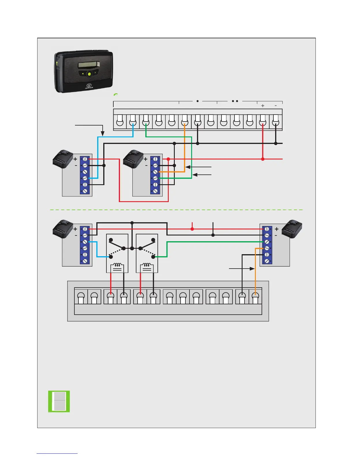
FIGURE 5
G-ULTRA RELAY 1 RELAY 2
GND IO1 IO2 IO3 IO4 NO NOCOM COMNC NC VDC
Possible Activations
• Arm / Disarm
To program the Strobe to Status:
JVA Keypad, Press:
1. “INSTALLER PIN”*0#
2. 2202#
3. *#
1. “INSTALLER PIN”*0#
2. 101# OR 0011# (Model Dependant)
3. *#
• Arm Status
• AlarmNotications
Electric Fence control board
GND
+12VDC
WiZo WiZo
WiZo WiZo
IN IN
IN IN
NO NO
NO NO
COM COM
COM COM
NC NC
NC NC
NONO
COM
++ --
NCNC
GND+12VDC
KEYSWITCH
KEYSWITCH
ALARM
STATUS
STATUS
ALARM
• TheStatusandalarminputsmusthavethreesecondsltertimeconguredon
the G-ULTRA
• The strobe output on the energiser needs to be programmed for the armed
statusnoticationtobesentviatheG-ULTRA
• Using “IN1” via the G-ULTRA will bypass the key-switch function on the energiser
8.2. Wiring a G-ULTRA into a Electric Fence Controller via WiZos
APPENDIXSECTION 8