page 34 www.centsys.com
Z1GND C
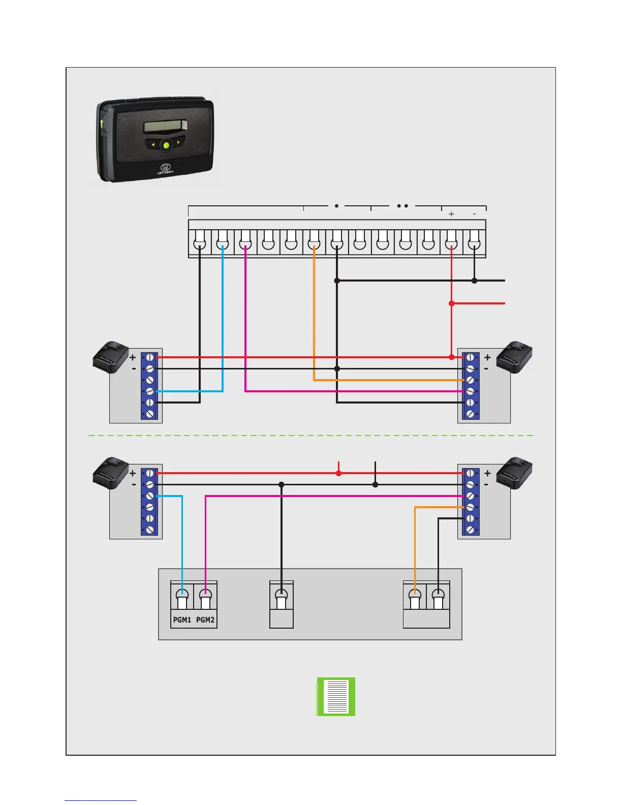
FIGURE 6
G-ULTRA RELAY 1 RELAY 2
GND IO1 IO2 IO3 IO4 NO NOCOM COMNC NC VDC
Possible Activations
• Arm / Disarm
Alarm programming:
PGM1: Armed Status
PGM2: Siren Follow
Z1: Keyswitch Latched Arm / Disarm
• Arm Status
• Intruder / Siren
Alarm Panel
GND
+12VDC
WiZo
WiZo
IN
IN
NO
NO
COM
COM
NC
NC
WiZo
IN
NO
COM
NC
WiZo
IN
NO
COM
NC
KEYSWITCH
KEYSWITCH
ALARM
ALARM
GND
STATUS
STATUS
GND+12VDC
The Alarm Panel PGMs must
activate to “GND”. However, if the
Alarm Panel only supports positive
activations, then relays must be
used between the Alarm Panel
and the G-ULTRA to change the
activation to “GND”.
8.3. Wiring a G-ULTRA into an Alarm System via WiZos
APPENDIXSECTION 8