chapter 7000
page 6
1,2 - 2,0 t A.C.
SERVICE MANUAL
Electric
036-0410-07
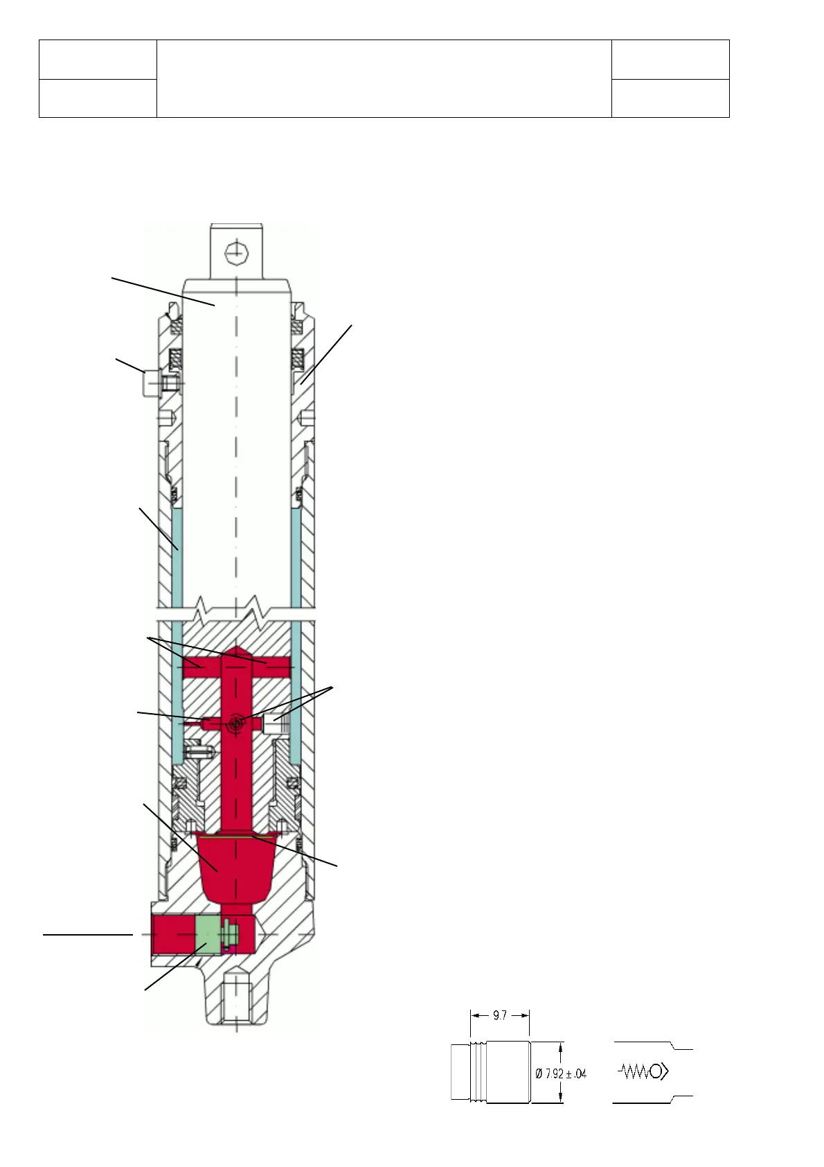
CENTRAL DISPLACEMENT CYLINDER WITH BRAKING EFFECT
ON THE LIFTING
The oil flows into the cylinder from the
“Oil inlet” when the control valve is
operated.
Flowing through channels 1, 2 and 3, it fills
chamber A until the inner oil pressure
exerts an upward force against the surface
C. The outward sliding of the rod is, thus,
set off. This movement is enacted by the
oil flow from chamber A to chamber B
through the above mentioned channels.
At the end of the expanding process
channels 1 and 2 are plugged by the cap.
Therefore, since the oil flowing between
the two chambers passes only through
channel 3, it has a lower capacity. The
outcome is a slowing-down or “Braking
effect”.
The downward sliding of the rod is
allowed by the opening of the “Oil inlet”
circuit, so that the oil can be retrieved
into the tank by means of the control
valve.
At the beginning of this phase chamber
A contains no oil. A more constant
filling is allowed by the two
unidirectional valves D and E that,
when open, permit avoiding jolts.
Once beyond the cap, the oil flow
between the two chambers passes
through channels 1 and 2, which are
now open.
Unidirectional
valves D-E
Rod
Bleeder
screw
Chamber A
Channels 1-2
Channels 3
Chamber B
Oil inlet
Safety valve
Surface C
Cap
>
Unidirectional
valves D-E