chapter 7000
page 7
1,2 - 2,0 t A.C.
SERVICE MANUAL
Electric
036-0410-07
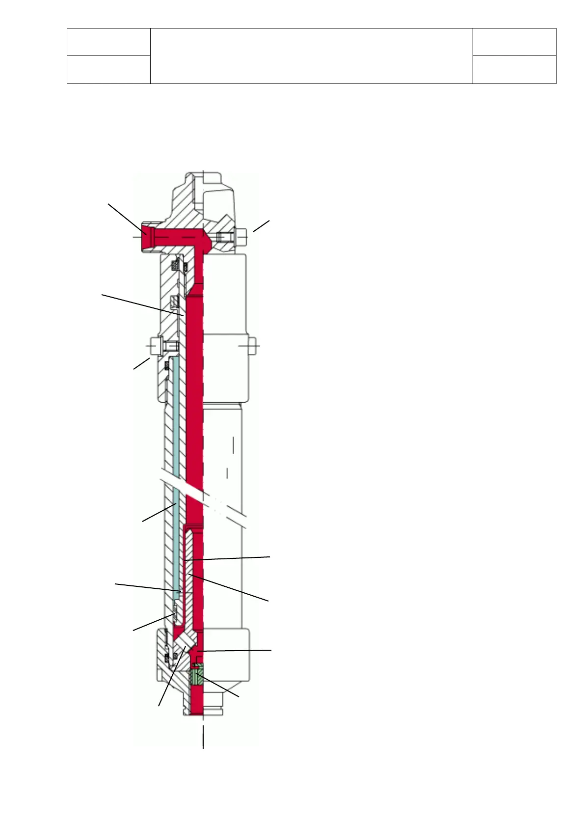
SIDE DISPLACEMENT CYLINDER WITH BRAKING EFFECT
ON THE LOWERING
The oil flows into the cylinder from the
“Oil inlet” when the control valve is
operated.
Flowing through chamber B and channel
A it fills first the central cylinders, then
chamber A through hole F and the
unidirectional valve C.
The oil exerts thus an upward force against
the surface D, which sets off the outward
sliding of the rod.
This movement is allowed by the oil flow
from chamber A to chamber B through
hole F and the guide ring.
The downward sliding of the rod is
allowed by the opening of the “Oil inlet”
circuit, so that the oil can be retrieved
into the tank by means of the control
valve.
In this phase the oil flows between the two
chambers only through the hole F, as
valve C is closed.
The downward speed of the rod remains
constant until hole F is closed by profile E.
The remarkable reduction of oil flow has
a slowing-down or “Braking effect”.
Safety valve
Oil inlet
Rod
Chamber A
blender
screw
Unidirectional
valve C
Surface D
Profile E
Hole F
Chamber A
Guide ring
Chamber B
bleeder
screw
Chamber B
Channel A
(to the central
cylinder)
>