chapter 7000
page 8
1,2 - 2,0 t A.C.
SERVICE MANUAL
Electric
036-0410-07
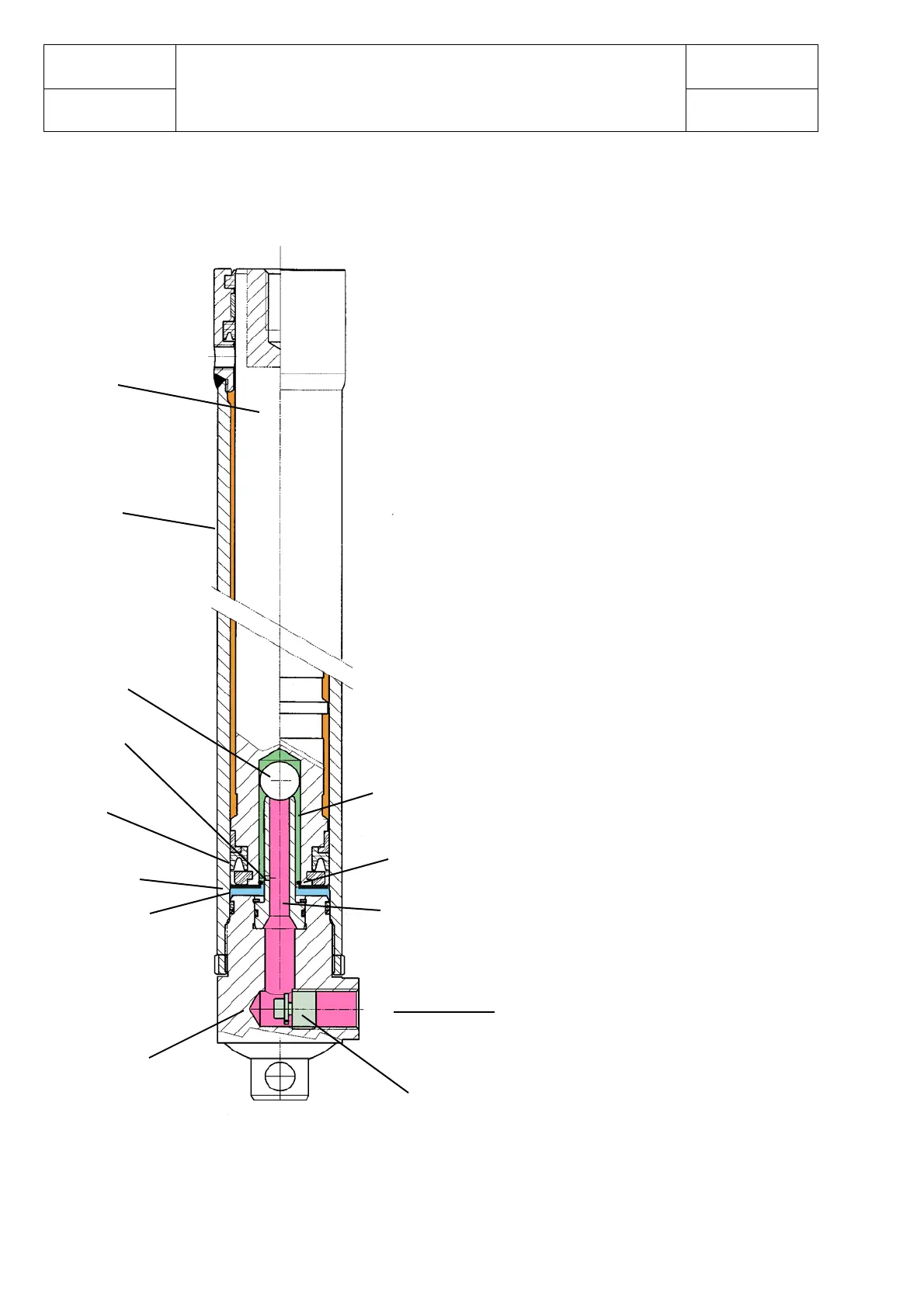
SIDE TELESCOPIC CYLINDER WITH BRAKING EFFECT
IN THE LOWERING (WITH SPHERE)
The oil flows into the cylinder from the
“Oil inlet” when the control valve is
operated.
Flowing through channels 1 and 2 and
thanks to the upward movement of the
sphere, the oil fills chamber A until the
inner oil pressure exerts an upward force
against surface C, obtaining the outward
sliding of the rod.
The snap ring is used to prevent the sphere
from sliding out of channel 2 while the rod
is moving, but freeing, all the same, the
passage of the oil between channel 2 and
chamber A.
The downward sliding of the rod is allowed
by the opening of the “Oil inlet” circuit, so
that the oil can be retrieved into the tank
by means of the control valve.
The drop of oil pressure in chamber A
causes the sphere to move to the
bottom of channel 2 and stop on the
snap ring.
In the beginning of this phase the oil
from chamber A flows all the way
through channel 1.
Only toward the end of its down-stroke
the sphere closes the top of channel 1,
thus directing the oil flow uniquely
through hole F.
This produces the hydraulic braking
effect in the lowering.
Chamber A
Surface C
Cap
Seals
Hole F
Sphere
Cylinder
Safety valve
Oil inlet
<
Channel 1
Channel 2
Rod
Snap ring