© Cesab 20 – 1 T Code(s): 841, 842, 843
Repair manual: Electrical components and wiring diagrams Model(s): S210, S212, S212S, S212L, S214, S214L,
S220D
Publication Number: 7588857-040 Date: 2018-05-01 Applies from serial number: 6384351-
20. Electrical components and wiring diagrams
20.1 Electric components
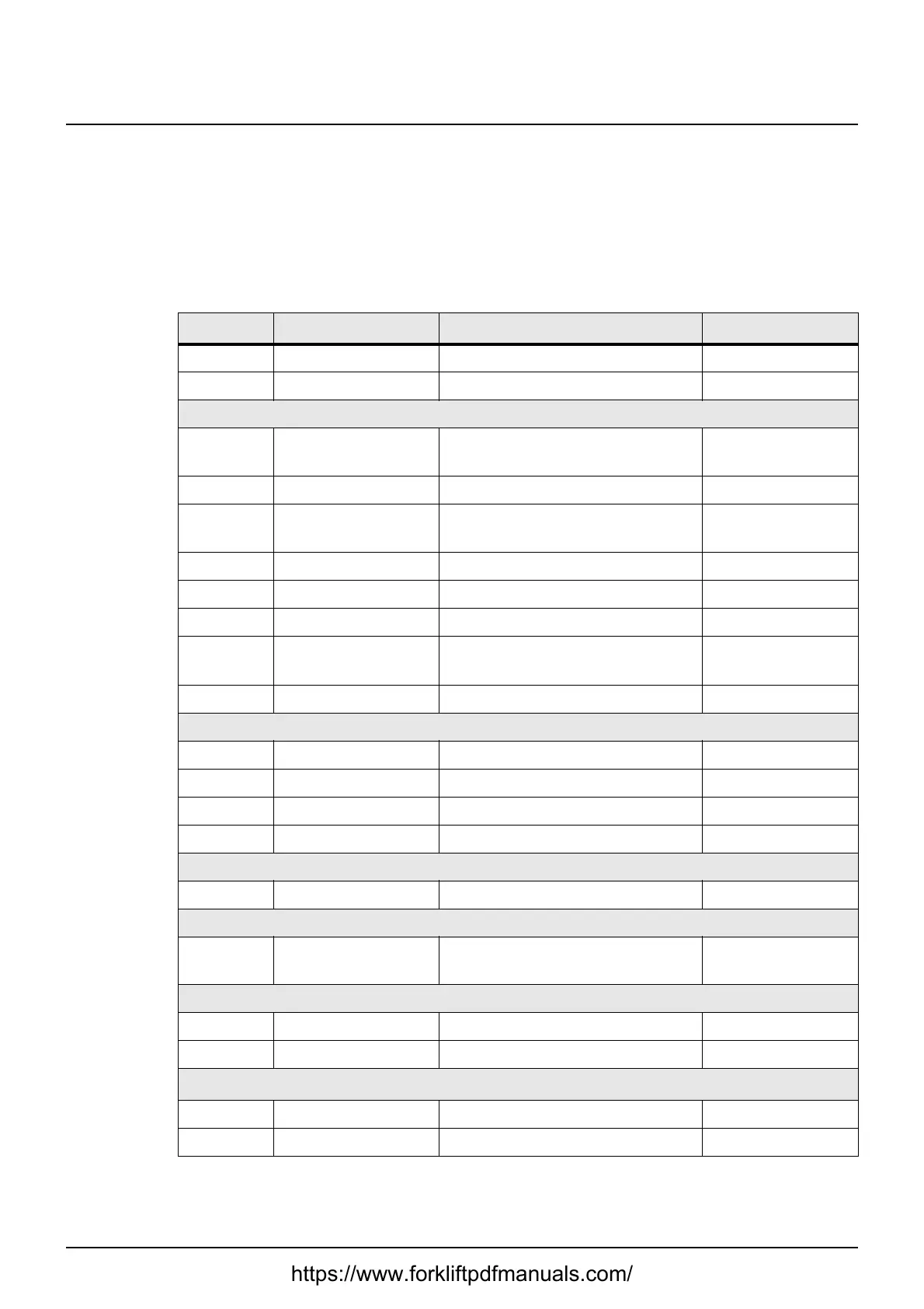
The table below shows a summary of the major electric components of this
truck.
Symbol Description Function Remarks
A5 Logic card Tiller arm logic card
A30 Battery charger On-board battery charger Option
B1 Temperature sen-
sor
Drive motor temperature sensor
B11 Pulse transformer Speed sensor
B60 Inductive switch Mechanical activation of the
brake
B62 Inductive switch Support arms, lowered position.
B63 Inductive switch Mast switch 1
B64 Inductive switch Mast switch 2
B65 Inductive switch Support arms, uppermost posi-
tion.
B90 Collision sensor Option
F1 Fuse Main fuse 150 A
F50 Fuse Operating circuit A5 7.5 A
F51 Fuse Operating circuit T1 7.5 A
F52 Fuse Optional equipment Option
G1 Battery 24 V
K110 Data Handling Unit
(DHU)
Data handling unit Option
M1 Motor Truck traction
M3 Motor Pump motor
P4 Horn
P5 Warning lamp Option
https://www.forkliftpdfmanuals.com/
 Loading...
