EasyManuals Logo

Cessna T182 Series User Manual

Cessna T182 Series
680 pages
To Next Page IconTo Next Page
To Previous Page IconTo Previous Page
Page #201 background imageLoading...
Page #201 background image
MODEL
182
&
T182
SERIES
SERVICE
MANUAL
7-4.
TROUBLE
SHOOTING
(Cont).
TROUBLE
PROBABLE
CAUSE
REMEDY
INCORRECT
FLAP
TRAVEL.
Incorrect
rigging.
Refer to
paragraph
7-18.
7-5.
FLAP
MOTOR
AND
TRANSMISSION
ASSEMBLY.
d.
Remove
remaining
items
by
removing
bolt
(28).
Use
care
not
to
drop
parts
into
tunnel
area.
7-6.
REMOVAL
AND
INSTALLATION.
(See
e.
Reverse
the
preceding
steps
for
reinstallation.
figure
7-2.)
Do
not
overtighten
bolt
(28)
causing
lever
(14)
to
bind.
a.
Run
flaps
to
full
DOWN
position.
Rig
system
in
accordance
with
paragraphs
7-18
and
b.
Disconnect
battery
ground
cable
and
insulate
7-19.
terminal
as
a
safety
precaution.
c.
Remove
access
plates
beneath
flap
motor
and
7-10.
DRIVE
PULLEYS.
(See
figure
7-2.)
transmission
assembly
in
right
wing.
7-11.
REMOVAL
AND
INSTALLATION.
NOTE
a.
Remove
access
plate adjacent
to
drive
pulley
(13)
in
right
wing.
Flap
motor
(9),
transmission
(7),
hinge
as-
b.
Unzip
or
remove
headliner
as
necessary
for
ac-
sembly
(10),
and
actuating
tube
(5)
are
re-
cess
to
turnbuckles
(index
4,
figure
7-1),
remove
moved
from
the
aircraft
as
a
unit.
On
air-
safety
wire
and
loosen
turnbuckles.
craft
equipped
with long
range
fuel
tanks,
it
c.
Remove
bolt
(19)
securing
flap
push-pull
rod
(14)
may
be
easier
to
detach
motor
and
trans-
to
drive
pulley
(13)
and
lower
RIGHT
flap
gently.
mission
assembly from
other
components
d.
Remove
bolt
(20)
securing
actuating
tube
(5)
to
before
removing
from
wing.
drive
pulley
(13)
and
lower LEFT
flap
gently. Retain
bushing.
d.
Remove
bolt
(20)
securing
actuating
tube
(5)
to
e.
Remove
cable
locks
(12)
securing
control
cables
drive
pulley
(13).
to
drive
pulley
(13).
Tag
cables
for reference
on
re-
e.
Screw
actuating
tube
(5)
in
toward
transmission
installation.
(7)
as
far
as
possible
by
hand.
f.
Remove
bolt
(11)
attaching
drive
pulley
(13)
to
f.
Remove
bolt
(1)
securing
flap
motor
hinge
(10)
wing
structure.
to
wing.
Retain
brass
washer
between
hinge and
wing
g.
Using
care,
remove
drive
pulley
through
access
structure
for
use
on
reinstallation.
opening,
being
careful
not
to
drop
bushing.
Retain
g.
Disconnect
motor
electrical
leads at
quick-dis-
brass
washer
between
drive
pulley
and
wing
structure
connects.
for
use
on
reinstallation.
Tape
open
ends
of
drive
h.
Disconnect
wiring
at
limit
switches
(23
and
26).
pulley
after
removal
to
protect
bearings.
i.
Carefully
work
assembly
from
wing
through
ac-
h.
To
remove
left
wing
drive
pulley,
use
this
same
cess
opening.
procedure
omitting
step
"d".
j.
Reverse
preceding
steps
for
reinstallation.
If
i.
Reverse
the
preceding
steps for
reinstallation.
hinge
assembly
(10)
was
removed
from
the
transmis-
Rig
system
in
accordance
with
paragraph
7-18,
safety
sion
(7)
for
any
reason,
ensure
that
short
end
of
turnbuckles
and
reinstall
all
items
removed
for
ac-
hinge
is
reinstalled
toward
the top.
cess.
k.
Use
Loctite
grade
CV
adhesive
on
threads
of
set-
screw
(6)
and
collar
(24)
whenever actuating
tube
(5)
7-12.
REPAIR.
Repair
is
limited to replacement
of
is
removed.
Torque
setscrew
to
40
inch-pounds.
bearings.
Cracked,
bent
or
excessively
worn
drive
1.
Complete
operational
check
as
outlined
in
para-
pulleys
must
be
replaced.
Lubricate bearings
as
out-
graph
7-3
and
rerig
system
in
accordance
with
para-
lined
in
Section
2.
graph 7-18
and
7-19.
7-13.
FLAPS. (See
figure
7-4.)
7-7.
REPAIR
Repair
consists
of
replacement
of
motor,
transmission,
actuating
tube
and
associated
7-14.
REMOVAL
AND
INSTALLATION.
hardware.
Bearings
in
hinge
assembly
may
also
be
a.
Run
flaps
to
full
DOWN
position.
replaced.
Lubricate
as
outlined
in
Section
2.
b.
Remove
access
plates
(1)
from
top leading
edge
of
flap.
7-8.
FLAP
CONTROL
LEVER
(See
figure
7-3.)
c.
Disconnect
push-pull
rod
(6)
at flap
bracket
(7).
d.
Remove
bolts
(5)
at
each
flap
track.
As
flap
is
7-9.
REMOVAL
AND
INSTALLATION.
removed
from
wing,
all
washers,
rollers
and
bush-
a.
Remove
follow-up
control
torque
tube
(17)
from
ings
will
fall free.
Retain
these
for
reinstallation.
switch
mounting
arm
(24).
e.
Reverse
the
preceding
steps
for reinstallation.
b.
Remove
flap
operating
switches
(23
and
25)
from
If
push-pull
rod
(6)
adjustment
is
not
disturbed,
re-
switch
mounting
arm
(24).
DO
NOT
disconnect
elec-
rigging
of
system
should
not
be
necessary.
Check
trical
wiring
at
switches.
flap
travel
and
rig
in
accordance
with
paragraph
7-18,
c.
Remove
knob
(15)
from
control
lever
(14).
if
necessary.
7-4

Table of Contents

Questions and Answers:

Question and Answer IconNeed help?

Do you have a question about the Cessna T182 Series and is the answer not in the manual?
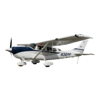
Cessna T182 Series Specifications

General IconGeneral
Engine TypeLycoming IO-540-AB1A5
Horsepower230 hp
Seating Capacity4
Service Ceiling18, 100 feet
Takeoff Distance1, 600 feet
Landing Distance1, 350 ft
TypeSingle-engine
Max Takeoff Weight3, 100 lb
Wingspan36 ft
Length29 ft
Height9 feet 3 inches
Fuel Capacity92 US gal (348 L)

Related product manuals