EasyManuals Logo

Cessna T182 Series User Manual

Cessna T182 Series
680 pages
To Next Page IconTo Next Page
To Previous Page IconTo Previous Page
Page #421 background imageLoading...
Page #421 background image
MODEL
182
&
T182
SERIES SERVICE
MANUAL
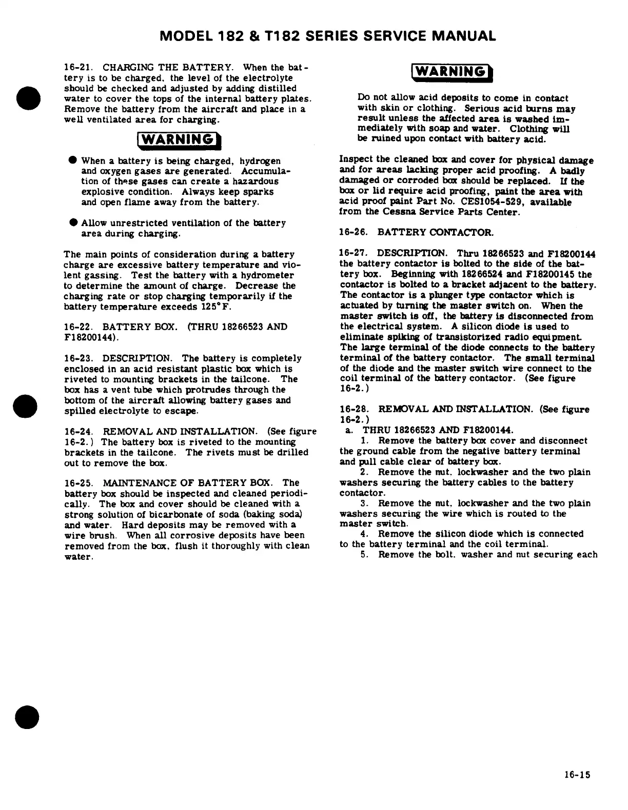
16-21.
CHARGING
THE
BATTERY.
When
the
bat-
tery
is
to be
charged,
the
level
of
the
electrolyte
should
be
checked
and
adjusted
by
adding
distilled
water
to
cover
the
tops
of
the
internal battery plates.
Do
not
allow
acid
deposits
to
come
in
contact
Remove
the
battery
from
the
aircraft
and
place
in
a
with
skin
or
clothing.
Serious
acid
burns
may
well
ventilated
area
for
charging.
result
unless
the
affected
area
is
washed
im-
mediately
with
soap
and
water.
Clothing
will
When
a
battery
is
being
charged,
hydrogen
Inspect
the
cleaned
box
and
cover
for
physical
damage
and
oxygen
gases
are
generated.
Accumula-
and
for
areas
lacking
proper
acid proofing.
A
badly
tion
of
these
gases
can
create
a
hazardous
damaged
or
corroded
box
should
be
replaced.
If
the
explosive
condition.
Always
keep
sparks
box
or
lid
require
acid
proofing,
paint
the
area
with
and
open
flame
away
from
the
battery.
acid
proof paint
Part
No.
CES1054-529,
available
from
the
Cessna
Service
Parts
Center.
Allow
unrestricted
ventilation
of
the
battery
area
during
charging.
16-26.
BATTERY
CONTACTOR.
The
main
points
of
consideration
during
a
battery
16-27.
DESCRIPTION.
Thru
18266523
and
F18200144
charge
are
excessive
battery
temperature
and
vio-
the
battery
contactor
is
bolted
to
the
side
of
the bat-
lent
gassing.
Test
the
battery
with
a
hydrometer
tery
box.
Beginning
with
18266524
and F18200145
the
to
determine
the
amount
of
charge.
Decrease
the
contactor
is
bolted
to
a
bracket
adjacent
to
the
battery.
charging
rate
or
stop
charging
temporarily
if the
The
contactor
is
a plunger
type
contactor
which is
battery
temperature
exceeds
125°F.
actuated
by
turning
the
master
switch
on.
When
the
master
switch
is
off,
the
battery
is
disconnected
from
16-22.
BATTERY
BOX.
(THRU 18266523
AND
the
electrical
system.
A
silicon
diode
is
used
to
F18200144).
eliminate
spiking
of
transistorized
radio
equipment
The
large
terminal
of
the
diode
connects
to
the
battery
16-23.
DESCRIPTION.
The
battery
is
completely
terminal
of
the
battery
contactor.
The
small
terminal
enclosed
in
an
acid
resistant
plastic
box
which
is
of
the
diode
and
the
master
switch
wire
connect
to
the
riveted
to
mounting
brackets
in
the
tailcone.
The
coil
terminal
of
the
battery
contactor.
(See
figure
box
has
a
vent
tube
which
protrudes
through
the
16-2.)
bottom
of
the
aircraft
allowing
battery gases
and
spilled
electrolyte
to
escape.
16-28.
REMOVAL
AND
INSTALLATION.
(See
figure
16-2.)
16-24.
REMOVAL
AND
INSTALLATION.
(See
figure
a.
THRU 18266523
AND
F18200144.
16-2.)
The
battery
box
is
riveted
to
the mounting
1.
Remove
the
battery
box
cover
and
disconnect
brackets
in
the
tailcone.
The
rivets
must
be
drilled
the
ground
cable
from
the
negative
battery
terminal
out
to
remove
the
box.
and
pull
cable
clear
of
battery
box.
2.
Remove
the
nut.
lockwasher
and
the
two
plain
16-25.
MAINTENANCE
OF
BATTERY
BOX.
The
washers
securing
the
battery
cables
to
the
battery
battery
box
should
be
inspected
and
cleaned
periodi-
contactor.
cally.
The
box
and
cover
should
be
cleaned
with
a
3.
Remove
the
nut.
lockwasher
and
the
two
plain
strong
solution
of
bicarbonate
of
soda
(baking
soda)
washers
securing
the
wire
which
is
routed
to
the
and
water.
Hard
deposits
may
be
removed
with
a
master
switch.
wire
brush.
When
all
corrosive
deposits
have
been
4.
Remove
the
silicon
diode
which
is
connected
removed
from
the
box.
flush
it
thoroughly
with
clean
to
the
battery
terminal
and
the
coil
terminal.
water.
5.
Remove
the
bolt. washer
and
nut
securing
each
16-15

Table of Contents

Questions and Answers:

Question and Answer IconNeed help?

Do you have a question about the Cessna T182 Series and is the answer not in the manual?

Cessna T182 Series Specifications

General IconGeneral
Engine TypeLycoming IO-540-AB1A5
Horsepower230 hp
Seating Capacity4
Service Ceiling18, 100 feet
Takeoff Distance1, 600 feet
Landing Distance1, 350 ft
TypeSingle-engine
Max Takeoff Weight3, 100 lb
Wingspan36 ft
Length29 ft
Height9 feet 3 inches
Fuel Capacity92 US gal (348 L)

Related product manuals