EasyManuals Logo

Cessna T182 Series User Manual

Cessna T182 Series
680 pages
To Next Page IconTo Next Page
To Previous Page IconTo Previous Page
Page #520 background imageLoading...
Page #520 background image
MODEL
182
&
T182
SERIES
SERVICE
MANUAL
WING
LOOKING
DOWN
AT
TOP
OF
LOWER
(10
REOD)
LOWER
WING
SKIN
(REF)
5.062
DIA-
S-225-4F
COVER
\,A | 4-
~
MS20426AD3
RIVETS
NOTE
PARTS
ARE
AVAILABLE
FROM
THE
CESSNA
SUPPLY
DIVISION.
S-1022Z-8-6
SCREWS
PRECAUTIONS
1.
Add
the
minimum
number
of
access
holes
necessary.
2.
Any
circular
or
rectangular
access
hole
which
is
used
with
approved
optional
equipment
installa-
tions
may
be
added
in
lieu
of
the
access
hole
illustrated.
3.
Use
landing
light
installations
instead
of
adding
access
holes
where
possible.
Do
not
add
access
holes
at
outboard
end
of
wing;
remove
wing
tip
instead.
4.
Do
not
add
an
access
hole
in
the
same
bay
where
one
is
already
located.
5.
Locate
new
access
holes
near
the
center
of
a
bay
(spanwise).
6.
Locate
new
access
holes
forward
of
the
front
spars
as
close
to
the
front
spar
as
practicable.
7.
Locate
new
access
holes
aft
of
the
front
spar
between
the
first
and
second
stringers
aft
of
the
spar.
When
installing
the
doubler,
rotate
it
so
the
two
straight
edges
are
closest
to
the
stringers.
8.
Alternate
bays,
with
new
access
holes
staggered
forward
and
aft
of
the
front
spar, are
pre-
ferable.
9.
A
maximum
of
five
new
access
holes
in
each
wing
is
permissible;
if
more
are
required,
contact
the
Cessna
Service
Department.
10.
When
a
complete
leading
edge
skin is
being
replaced,
the
wing
should
be
supported
in
such
a
manner
so that
wing
alignment
is
maintained.
a.
Establish
exact
loca'ton
for
inspection
cover
and
inscribe
centerlines.
b.
Determine
position
of
doubler
on
wing
skin
and
center
over
centerlines.
Mark
the
ten
rivet
hole
locations
and
drill
to
size
shown.
c.
Cutout
access
hole,
using
dimension
shown.
d.
Flex doubler
and
insert
through
access
hole,
and
rivet
in
place.
e.
Position
cover
and
secure,
using
screws
as
shown.
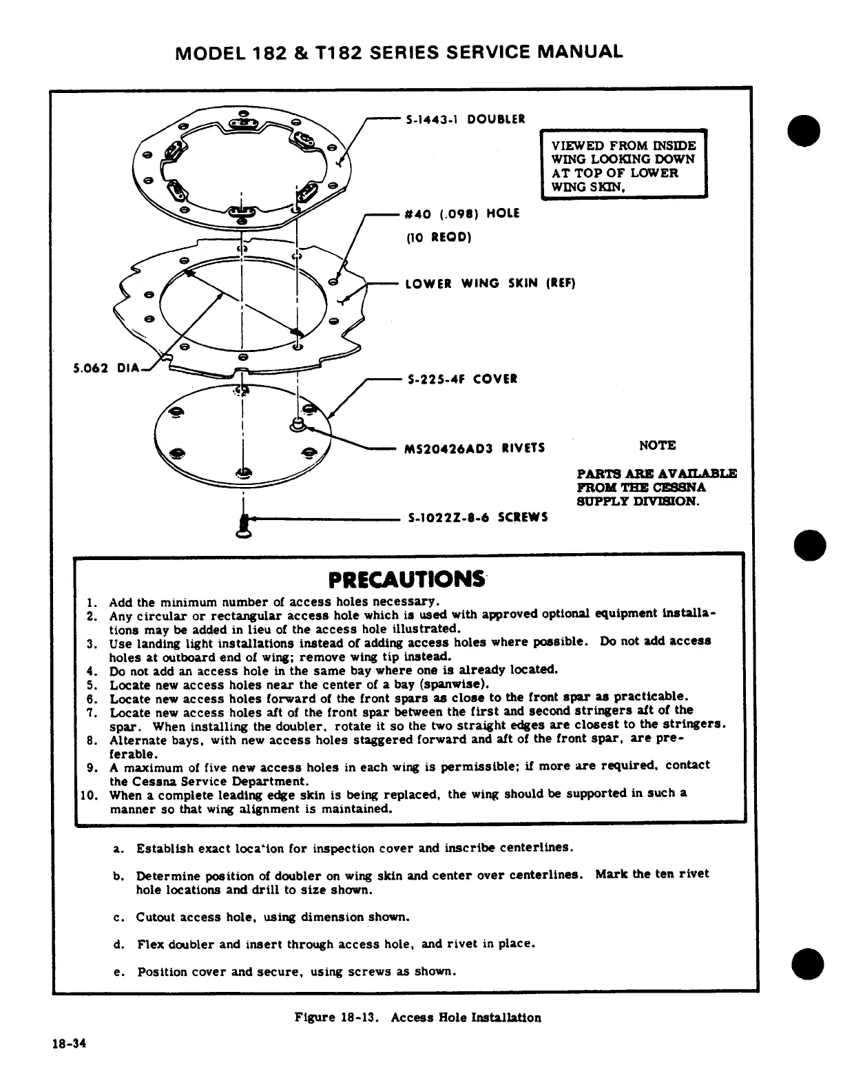
Figure
18-13.
Access
Hole
Installation
18-34

Table of Contents

Questions and Answers:

Question and Answer IconNeed help?

Do you have a question about the Cessna T182 Series and is the answer not in the manual?

Cessna T182 Series Specifications

General IconGeneral
Engine TypeLycoming IO-540-AB1A5
Horsepower230 hp
Seating Capacity4
Service Ceiling18, 100 feet
Takeoff Distance1, 600 feet
Landing Distance1, 350 ft
TypeSingle-engine
Max Takeoff Weight3, 100 lb
Wingspan36 ft
Length29 ft
Height9 feet 3 inches
Fuel Capacity92 US gal (348 L)

Related product manuals