EasyManuals Logo

Cessna T182 Series User Manual

Cessna T182 Series
680 pages
To Next Page IconTo Next Page
To Previous Page IconTo Previous Page
Page #402 background imageLoading...
Page #402 background image
MODEL
182
&
T182
SERIES SERVICE
MANUAL
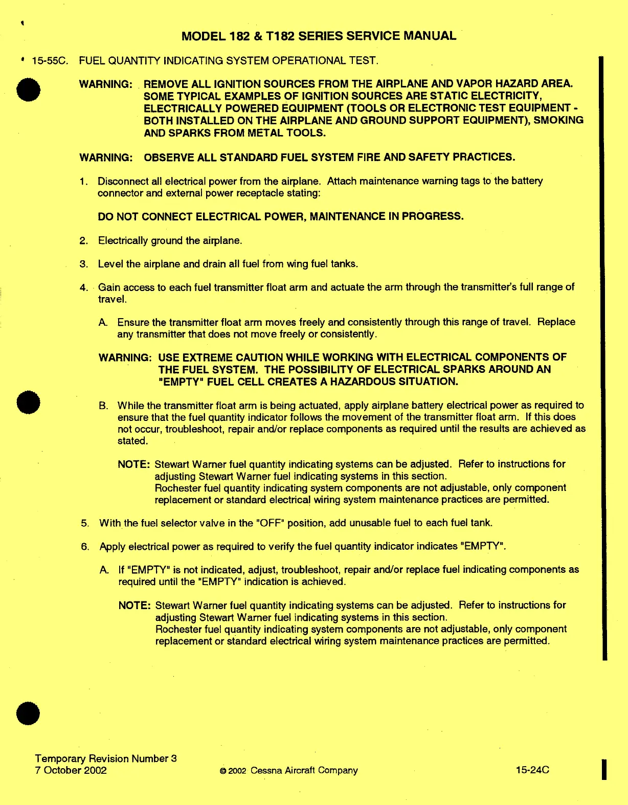
15-55C.
FUEL
QUANTITY
INDICATING
SYSTEM
OPERATIONAL
TEST.
WARNING:
REMOVE
ALL
IGNITION
SOURCES
FROM
THE
AIRPLANE
AND
VAPOR
HAZARD
AREA.
SOME
TYPICAL
EXAMPLES
OF
IGNITION
SOURCES
ARE
STATIC ELECTRICITY,
ELECTRICALLY
POWERED
EQUIPMENT
(TOOLS
OR
ELECTRONIC
TEST
EQUIPMENT
-
BOTH
INSTALLED
ON
THE
AIRPLANE
AND
GROUND
SUPPORT
EQUIPMENT),
SMOKING
AND
SPARKS
FROM
METAL
TOOLS.
WARNING:
OBSERVE
ALL
STANDARD
FUEL
SYSTEM
FIRE
AND
SAFETY
PRACTICES.
1.
Disconnect
all
electrical
power
from
the airplane.
Attach
maintenance
warning
tags
to
the
battery
connector
and
external
power
receptacle
stating:
DO
NOT
CONNECT
ELECTRICAL
POWER,
MAINTENANCE
IN
PROGRESS.
2.
Electrically
ground
the
airplane.
3.
Level
the
airplane
and
drain
all fuel
from wing
fuel
tanks.
4.
Gain
access
to
each
fuel transmitter
float
arm
and
actuate
the
arm
through
the transmitter's
full
range
of
travel.
A.
Ensure
the
transmitter
float
arm
moves
freely
and
consistently
through
this
range
of
travel.
Replace
any
transmitter
that
does
not
move
freely
or
consistently.
WARNING:
USE
EXTREME
CAUTION
WHILE
WORKING
WITH
ELECTRICAL
COMPONENTS
OF
THE
FUEL
SYSTEM. THE
POSSIBILITY
OF
ELECTRICAL
SPARKS
AROUND
AN
"EMPTY"
FUEL
CELL
CREATES
A
HAZARDOUS
SITUATION.
B.
While
the
transmitter
float
arm is
being actuated,
apply
airplane
battery
electrical
power
as
required
to
ensure
that
the
fuel
quantity indicator
follows
the
movement
of
the
transmitter
float
arm.
If
this does
not
occur,
troubleshoot,
repair
and/or
replace
components
as
required
until
the
results
are
achieved
as
stated.
NOTE:
Stewart
Warner
fuel
quantity indicating
systems
can
be
adjusted.
Refer
to
instructions
for
adjusting
Stewart
Warner
fuel
indicating
systems
in
this section.
Rochester
fuel
quantity indicating
system
components
are
not
adjustable,
only
component
replacement
or
standard
electrical
wiring
system
maintenance
practices
are
permitted.
5.
With
the fuel
selector
valve
in
the
"OFF"
position,
add
unusable
fuel to
each
fuel
tank.
6.
Apply
electrical
power
as
required
to
verify
the
fuel
quantity
indicator
indicates
"EMPTY".
A.
If
"EMPTY"
is
not
indicated,
adjust,
troubleshoot,
repair
and/or
replace
fuel
indicating
components
as
required until
the
"EMPTY"
indication
is
achieved.
NOTE:
Stewart
Warner
fuel
quantity
indicating
systems
can
be
adjusted.
Refer
to
instructions
for
adjusting
Stewart
Warner
fuel
indicating
systems
in
this
section.
Rochester
fuel
quantity
indicating
system
components
are
not
adjustable, only
component
replacement
or
standard
electrical
wiring
system
maintenance
practices
are
permitted.
Temporary
Revision
Number
3
7
October
2002
©
2002
Cessna
Aircraft
Company
15-24C

Table of Contents

Questions and Answers:

Question and Answer IconNeed help?

Do you have a question about the Cessna T182 Series and is the answer not in the manual?

Cessna T182 Series Specifications

General IconGeneral
Engine TypeLycoming IO-540-AB1A5
Horsepower230 hp
Seating Capacity4
Service Ceiling18, 100 feet
Takeoff Distance1, 600 feet
Landing Distance1, 350 ft
TypeSingle-engine
Max Takeoff Weight3, 100 lb
Wingspan36 ft
Length29 ft
Height9 feet 3 inches
Fuel Capacity92 US gal (348 L)

Related product manuals