EasyManuals Logo

Cessna T182 Series User Manual

Cessna T182 Series
680 pages
To Next Page IconTo Next Page
To Previous Page IconTo Previous Page
Page #435 background imageLoading...
Page #435 background image
MODEL
182
&
T182
SERIES
SERVICE
MANUAL
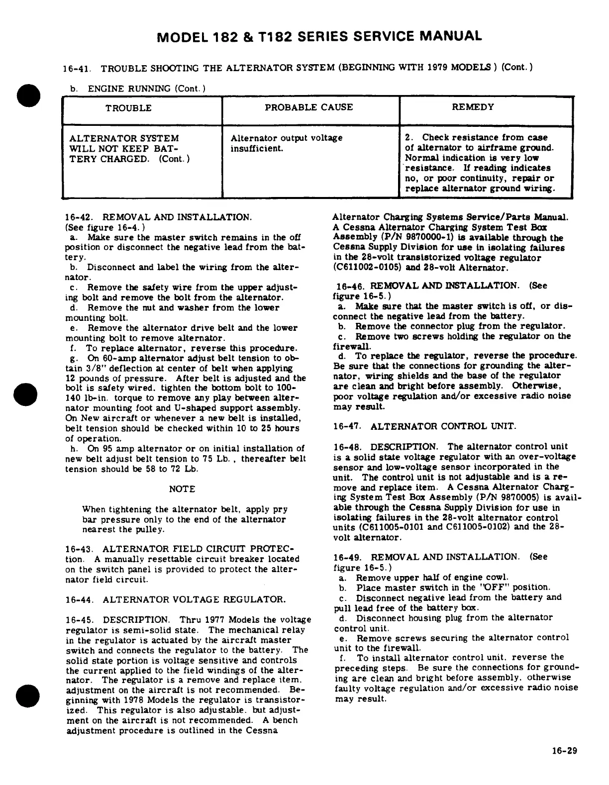
16-41.
TROUBLE
SHOOTING
THE
ALTERNATOR
SYSTEM
(BEGINNING
WITH 1979
MODELS)
(Cont.)
.
b.
ENGINE
RUNNING
(Cont.)
TROUBLE
PROBABLE
CAUSE
REMEDY
ALTERNATOR
SYSTEM
Alternator
output
voltage
2.
Check
resistance
from
case
WILL
NOT
KEEP
BAT-
insufficient,
of
alternator
to
airframe
ground.
TERY
CHARGED.
(Cont.)
Normal
indication
is
very
low
resistance.
If
reading
indicates
no,
or
poor
continuity,
repair
or
replace
alternator
ground
wiring.
16-42.
REMOVAL
AND
INSTALLATION.
Alternator
Charging
Systems
Service/Parts
Manual.
(See
figure
16-4.
)
A
Cessna
Alternator
Charging
System
Test
Box
a.
Make
sure
the
master
switch
remains
in
the
off
Assembly
(P/N
9870000-1)
is
available
through
the
position
or
disconnect
the
negative
lead
from
the
bat-
Cessna
Supply
Division
for
use
in
isolating
failures
tery.
in
the
28-volt
transistorized
voltage
regulator
b.
Disconnect
and
label
the
wiring
from
the
alter-
(C611002-0105)
and
28-volt
Alternator.
nator.
c.
Remove
the
safety
wire
from
the
upper
adjust-
16-46.
REMOVAL
AND
INSTALLATION.
(See
ing
bolt
and
remove
the
bolt
from
the
alternator.
figure
16-5.)
d.
Remove
the
nut
and
washer
from
the
lower
a.
Make
sure
that
the
master
switch
is
off,
or
dis-
mounting
bolt.
connect
the
negative lead
from
the
battery.
e.
Remove
the
alternator
drive
belt
and
the
lower
b.
Remove
the
connector
plug
from
the
regulator.
mounting
bolt
to
remove
alternator.
c.
Remove
two
screws
holding
the
regulator
on
the
f.
To
replace
alternator,
reverse
this
procedure.
firewall.
g.
On
60-amp
alternator
adjust
belt
tension
to
ob-
d.
To
replace
the
regulator,
reverse
the
procedure.
tain
3/8"
deflection
at
center
of
belt
when
applying
Be
sure
that
the
connections
for
grounding
the
alter-
12
pounds
of
pressure.
After belt
is
adjusted
and
the
nator,
wiring
shields
and
the
base
of
the
regulator
bolt is
safety
wired.
tighten
the
bottom
bolt
to
100-
are
clean
and
bright
before
assembly. Otherwise,
140
lb-in.
torque
to
remove
any
play
between
alter-
poor voltage
regulation
and/or
excessive
radio
noise
nator
mounting
foot
and
U-shaped
support assembly.
may
result.
On
New
aircraft
or
whenever
a
new
belt
is
installed,
belt
tension
should
be
checked
within
10
to
25
hours
16-47.
ALTERNATOR
CONTROL
UNIT.
of
operation.
h.
On
95
amp
alternator
or
on
initial
installation
of
16-48.
DESCRIPTION.
The
alternator
control
unit
new
belt
adjust
belt
tension
to
75
Lb.,
thereafter
belt
is
a
solid
state
voltage
regulator
with
an
over-voltage
tension
should
be
58
to
72
Lb.
sensor
and
low-voltage
sensor
incorporated
in
the
unit.
The
control
unit
is
not
adjustable
and
is
a
re-
NOTE
move
and
replace
item.
A
Cessna
Alternator
Charg-
ing
System
Test
Box
Assembly
(P/N
9870005)
is
avail-
When
tightening
the
alternator
belt,
apply
pry able
through
the
Cessna
Supply
Division
for
use
in
bar
pressure
only
to
the
end
of
the
alternator
isolating
failures
in
the
28-volt
alternator
control
nearest
the
pulley.
units
(C611005-0101
and
C611005-0102)
and
the
28-
volt
alternator.
16-43.
ALTERNATOR
FIELD
CIRCUIT
PROTEC-
tion.
A
manually
resettable circuit
breaker
located 16-49.
REMOVAL
AND
INSTALLATION.
(See
on
the
switch
panel
is
provided
to
protect
the
alter-
figure
16-5.)
nator
field
circuit.
a.
Remove
upper
half
of
engine
cowl.
b.
Place
master
switch
in
the
"OFF" position.
16-44.
ALTERNATOR
VOLTAGE REGULATOR.
c.
Disconnect negative
lead
from
the
battery
and
pull lead
free
of
the
battery
box.
16-45.
DESCRIPTION.
Thru
1977
Models
the
voltage
d.
Disconnect
housing
plug
from
the
alternator
regulator
is
semi-solid
state.
The
mechanical
relay control
unit.
in
the
regulator
is
actuated
by
the
aircraft
master
e.
Remove
screws
securing
the
alternator
control
switch
and
connects
the
regulator
to
the
battery.
The
unit
to
the
firewall.
solid
state
portion
is
voltage
sensitive
and
controls
f.
To
install
alternator
control
unit.
reverse
the
the
current
applied
to
the
field
windings
of
the
alter-
preceding
steps.
Be
sure
the
connections
for
ground-
nator.
The
regulator
is
a
remove
and
replace
item.
ing
are
clean
and
bright
before
assembly.
otherwise
adjustment
on
the
aircraft
is
not
recommended.
Be-
faulty
voltage
regulation
and/or excessive
radio
noise
ginning
with
1978
Models
the
regulator
is
transistor-
may
result.
ized.
This
regulator
is
also
adjustable.
but
adjust-
ment
on
the
aircraft
is
not
recommended.
A
bench
adjustment
procedure
is
outlined
in
the
Cessna
16-29

Table of Contents

Questions and Answers:

Question and Answer IconNeed help?

Do you have a question about the Cessna T182 Series and is the answer not in the manual?

Cessna T182 Series Specifications

General IconGeneral
Engine TypeLycoming IO-540-AB1A5
Horsepower230 hp
Seating Capacity4
Service Ceiling18, 100 feet
Takeoff Distance1, 600 feet
Landing Distance1, 350 ft
TypeSingle-engine
Max Takeoff Weight3, 100 lb
Wingspan36 ft
Length29 ft
Height9 feet 3 inches
Fuel Capacity92 US gal (348 L)

Related product manuals