15
WIRING
Install Entrapment Protection Devices
Refer to Accessories page for the approved list of entrapment protection devices.
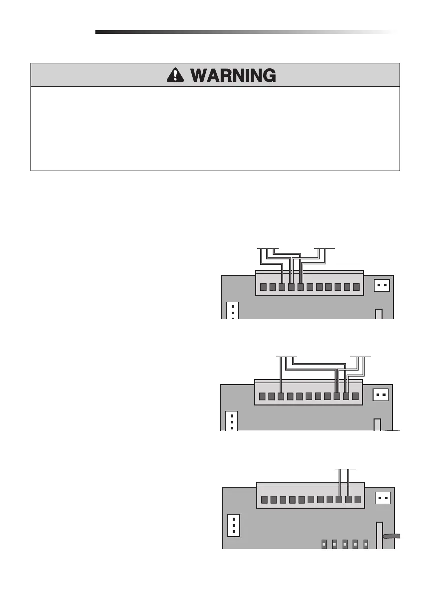
PHOTOELECTRIC SENSORS
The photoelectric sensor will function differently
depending on if it is connected to the IR1 or IR2
input. Refer to the "Settings" section on page 22 for
an explanation of the functionality.
1. Remove the factory jumper from the IR1 or IR2
input.
2. Connect the photoelectric sensor receiver to
IR1 and GND or IR2 and GND, depending on
the desired functionality.
3. Connect the photoelectric sensor transmitter to
IR+24V, IR1, and GND or to IR+24V, IR2, and
GND.
EDGE SENSOR
The Edge sensor can only be connected to the IR2
input.
1. Remove factory jumper from IR2 to GND.
2. Connect the edge sensor to IR2 and GND.
To prevent SERIOUS INJURY or DEATH from a moving gate:
• Entrapment protection devices MUST be installed to protect anyone who may come near a
moving gate.
• Locate entrapment protection devices to protect in BOTH the open and close gate cycles.
• Locate entrapment protection devices to protect between moving gate and RIGID objects, such as
posts or walls.
STOP
GND
IR2
SW2
SW1
GND
IR1
IR+24V
DCLAMP
+24V
CN3
CN2
CONTROL BOARD
Photoelectric
Sensor Receiver
IR1 Functionality
Photoelectric
Sensor Transmitter
STOP
GND
IR2
SW2
SW1
GND
IR1
IR+24V
DCLAMP
+24V
CN3
CN2
CN4
LED1
LED2
LED3
LED4
LED5
Edge Sensor
CONTROL BOARD
STOP
GND
IR2
SW2
SW1
GND
IR1
IR+24V
DCLAMP
+24V
CN3
CN2
IR2 Functionality
CONTROL BOARD
Photoelectric
Sensor Receiver
Photoelectric
Sensor Transmitter