10
Clearances
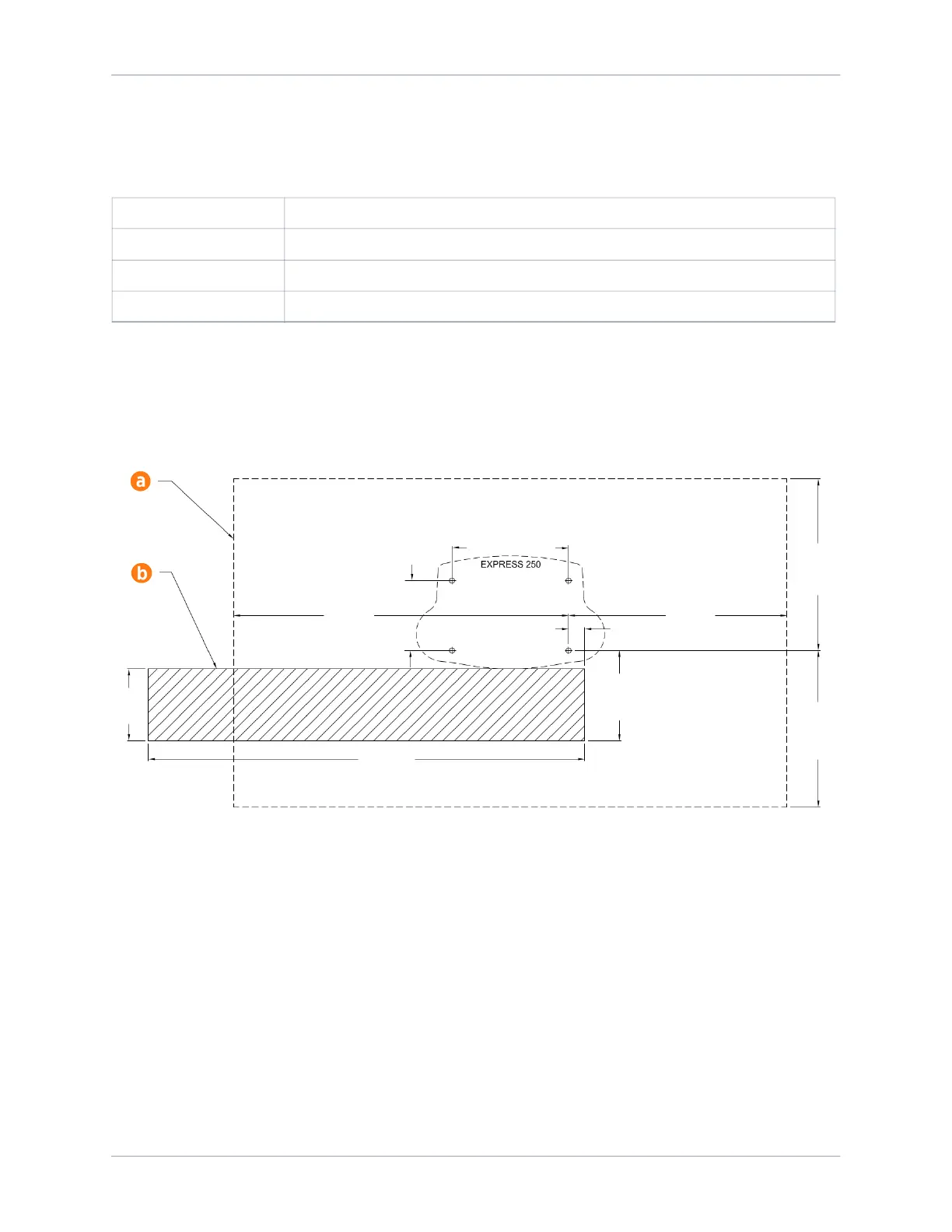
The Express 250 requires minimum functional and service clearances as listed in the table below.
* Side clearance is measured from extrusion to extrusion.
** Side clearance can be shared between two charging stations. However, if the charge handles of
both stations are facing each other, add an extra 254 mm (10 in).
Measurements are provided in millimeters (inches).
a. Service clearance of open space (not necessarily at system grade)
b. Power Module service clearance at grade from the front right anchor, extending 1700 mm (67
in) to the left, without any permanent obstructions (fencing, bollards, wheel stops, etc.)
Note: Listed side clearances are the minimum required for operation and service. For paired
charging stations, the bend radius of the DC cable and conduit might require spacing them further
apart.
Rear clearance, and the front and side clearance for Power Module service, must be at grade level
+/- 25 mm (1 in).
Refer to the “Ventilation” section, and check local and regional code, for any additional clearance
requirements.
Front Clearance 330.2 mm (13 in) at grade; 609.6mm (24 in) minimum open space
Side Clearance* 711.2 mm (28 in) required; 863.6 mm (34 in) recommended**
Rear Clearance 304.8 mm (12 in) required; 609.6 mm (24 in) recommended
Top Clearance 304.8 mm (12 in)
280
(11)
352
(14)
1305
(51.4)
610
(24)
63 (2.5)
666
(26)
1700
(67)
851
(33.5)
271
(10.7)
454
(17.9)