23
• DC conductors (x4):
• NOTE: 95 mm
2
(3/0 AWG) is sufficient for most sites unless ambient temperatures are
>= 40°C per regional code (ASHRAE Table D101 Summer Dry Bulb Temperature for North
America or IEC 60364-5-54 in Europe)
• 2 positive and 2 negative conductors; 1 positive and 1 negative in each direction
• USA/Canada: Copper only, minimum current carrying capacity 160 A
• EU/UK: Rated at 1000 V conductor to conductor (+/-500 V conductor to ground, LV), copper
only, minimum current carrying capacity 160 A
• DC cable run must be continuous, with no joints or splices
• Consult site drawings for site-specific conductor size and length (Appendix A provides
conductor size calculation examples for reference)
• Leave 61 cm (2 ft) of each conductor above grade at each end
• DC lugs (x4):
• Silver plated copper compression lug (2-hole specified for North America); tin plated is
acceptable if used with dielectric grease
• Holes for an M6 (1/4 in) stud at 19 mm (3/4 in) stud hole spacing
• Maximum width 30 mm (1.18 in)
• NOTE: 95 mm
2
(3/0 AWG) is sufficient for most sites unless ambient temperatures are
>= 40°C per regional code (ASHRAE Table D101 Summer Dry Bulb Temperature for North
America or IEC 60364-5-54 in Europe)
• North America lug size: 3/0 or 4/0 AWG
• Example UK/EU lugs for average conductor size are Weidmuller 1494410000 120 mm
2
or
similar (always review the lug manufacturer’s instructions for crimper tool and die
compatibility)
• Contact ChargePoint if the installer requires lugs for 3/0 (kit 99-002644) or 4/0 (kit 99-
002645) conductors
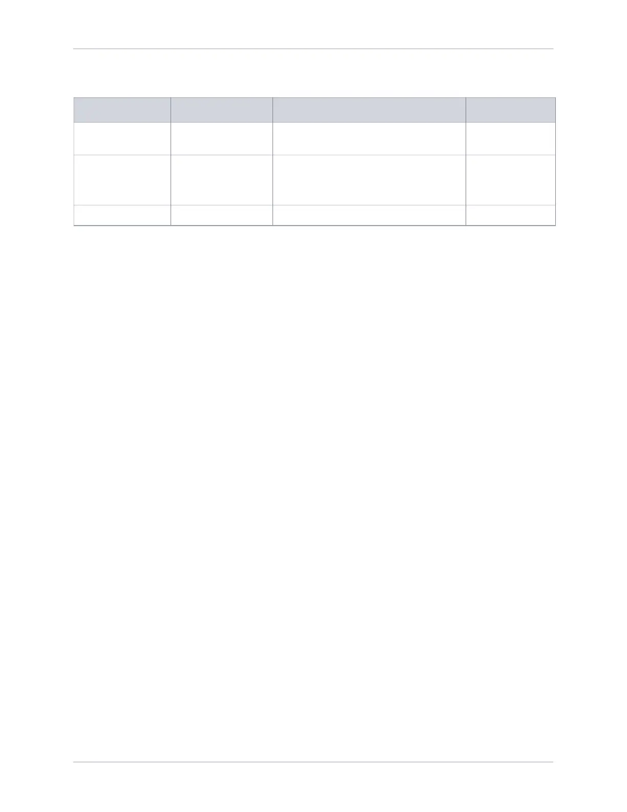
Voltage Rating Temperature Rating Maximum Conductor Size for Terminals Insulation Type
EU non-armored:
600/1000 V
90°C
120 mm
2
XLPE
EU armored:
600/1000 V
90°C
120 mm
2
4-core and cable gland sized
to local code (such as Cablecraft
CCG-CW50 or similar)
XLPE
NA: 1000 V 90°C 4/0 AWG XHHW-2