DF II Series User Manual 71
CONTACT CLOSURE OPERATION
Thecontactclosurefeaturemustbespeciedin
the gauge setup and the gauge must be placed in
Contact Closure Mode. When in Contact Closure
mode, the DFS II Series gauge will “freeze” the
display at the load that caused a switch “make” or
“break”.
The DFS II Series gauge must have a cable that
jumpers Pins 8 and 10 and that connects the
switch to the force gauge.
CONTACT CLOSURE MODE
The DFS II Series will indicate that the gauge is in
the Contact Closure mode. The mode indicator will
display as “OFRZ” for a “break” setup or as “CFRZ”
for a “make” setup. The load measurement will
represent the actual load that was sensed by the
gauge when the switch was “opened” of “closed”.
Units may be changed and results may be saved in
the gauge memory for statistical calculations.
CONTACT CLOSURE PASS-FAIL
The DFS II Series gauge’s Pass-Fail feature can
be used with the Contact Closure Mode. Pass
orFaillimitsmaybeconguredbytheuserinthe
gauge setup. When this feature is enabled, the
DFS II Series gauge will display a green “PASS” or
ared“FAIL”basedonthelimitsthatwerecong-
ured and the load that is displayed by the gauge.
The Pass or Fail limits may be based on a RANGE
or on a NOMINAL VALUE with BANDWIDTH. See
“Using Pass-Fail Limits” for more information.
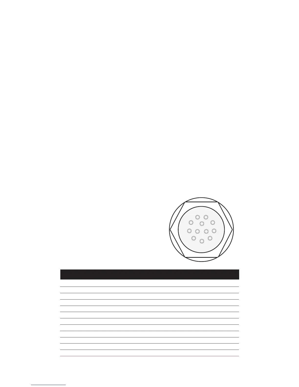
1 TXD O RS-232 Transmitted Data
2 RXD I RS-232 Received Data
3 GND O Ground Digital Ground
4 O Clock Mitutoyo Clock
5 O Ready Mitutoyo Ready
6 I Request Mitutoyo Request
7 O Data Mitutoyo Data
8 I Detect Sense Contact Closure
9 O Setpoint Setpoint Output Signal
10 - Ground Digital Ground
11 - Analog GND Analog Ground
12 O Analog SIG Analog Output
PIN SYMBOL I/O PURPOSE DESCRIPTION
9
8
7
6
5
4
3
2
1
10
12
11