NVF5 Series User Manual Appendix A RS485-MODBUS
Communication Instructions
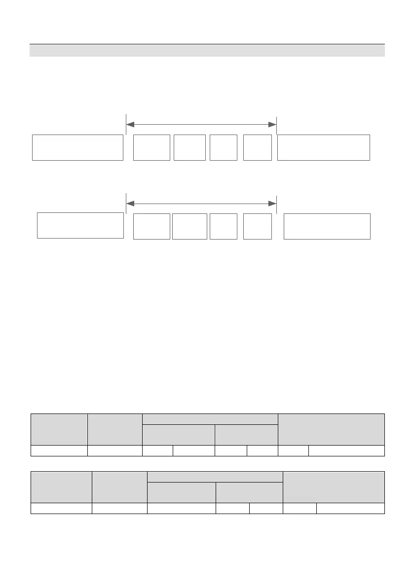
A.4 Protocol Format
Modbus protocol supports both RTU and ASCII modes. The corresponding frame
format is shown below.
Start
(
at least 3.5 characters free)
RTU Mode
Slave
address
Command
code
Data
Check
code
End
(at least 3.5 characters free)
Modbus data frame
Start
(0x3A)
ASCII mode
End
(0x0D,frame tail bytes)
Slave
address
Command
code
Data
Check
code
Modbus data frame
Figure A-4-1 Modbus Protocol Format
Modbus adopts “Big Endian” encoded mode,and sends the upper byte and then the
lower byte.
A.4.1 RTU Mode
In RTU mode, the bigger one between the function code and Modbus internal
convention value is taken for the free time between frames. The minimum free time
between frames internally agreed by Modbus is as follows: free time of frame head and tail
is not less than 3.5-byte time to define the frame. Data check adopts CRC-16; the whole
information participates in the check; upper and lower bytes of the checksum should be
sent after exchange. Refer to the examples following the reference protocol for the specific
CRC check. Note, at least 3.5-character Bus free time should be kept among frames; Bus
free among frames does not need to accumulate the start and end free.
The following examples show how to read the parameters of the internal register
0x0101(F1.01)of slave 5 in RTU mode.
Request frame:
Slave
Address
Command
Code
Check Code
Read Bytes
Request frame:
Slave
Address
Command
Code
Check Code
The check code is CRC check value.
A.4.2 ASCII Mode
- 102 -