NVF5 Series User Manual Appendix A RS485-MODBUS
Communication Instructions
parameters
in Group Max
0x43xx
(xx= Max-1)
Obtain the number of
Max
A.8 Network Wiring
A.8.1 Topology structure
RS-485-Modbus repeater is not configured. There is a trunk cable which is directly
connected with all devices (daisy-chained) or connected through short branch cable.
Trunk cable, also known as Bus, may be very long. The termination resistor must be
connected at the each end of the network cable. Also the repeater can be used among
multiple RS-485 Modbus. And each slave address in the network is unique, which is the
basis for guaranteeing Modbus serial communications.
A.8.2 Length
End-to-end length of the trunk cable must be limited. Maximum length is related to
Baud rate, load quantity on the cable (specification, capacitance, or characteristic
impedance) and daisy chain and network configuration (2-wire or 4-wire system).
Branches must be short and cannot exceed 20m. If multi-port splitter with n branches,
the maximum length of each branch must be restricted to 40m divided by n.
A.8.3 Grounding Mode
“Network Common” circuit (common end of the signal and optional power supply)
must be directly connected to PE ground. It’s better that the whole Bus is grounded in a
single point. Usually, this point is optional on the master or its splitter.
A.8.4 Cable
Modbus cable on the serial link must be shielded. At each end of the cable, shield
must be connected to the PE ground. If the connector is used in this end, the connector
housing should be connected to the cable shielding layer. RS485-Modbus must use a pair
of lines and the third line (for common end).
For RS485-Modbus, cable of diameter wide enough must be selected to allow the use
of maximum length (1000m). AWG24 can meet the needs of Modbus data transmission.。
A.9 Definition of Communication Exception Code
When the corresponding error message is detected in the communication process,
the lower machine (i.e., CPU ) will be position “1” of the function code, and feedback
corresponding error code (exception code), to recognize the current error for the host
computer. The corresponding definitions are shown in Table A.6.
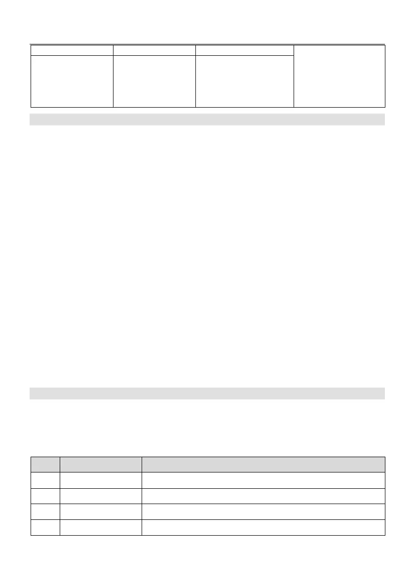
Table A.6 Definition of Communication Exception Code
0 0x00 No error information
1 0x01 Illegal function number
2 0x02 Illegal data address
3 0x03 Illegal data value
- 109 -