NVF5 Series User Manual Chapter 3 Installation and Wiring
R is actual brake resistor resistance,P
is brake resistor power.
3.2.3 Output AC Reactor Descriptions
The cable between Inverter and Motor should not be too long.If the cable is too long,the
distributed capacitance will be large, the harmonic current will be generated easily.
The output AC reactor should be selected when the motor cable is too long.Please refer
to the table below:
Catalog No.
Current
Min.Cable Length
(m)
AC output reactor
NVF5-0.4/TS4-B 1.5 50
NVF5-0.75/TS4-B 2.7 50
NVF5-1.5/TS4-B 4.2 50
NVF5-2.2/TS4-B 5.8 50
NVF5-3.7/TS4-B 10.5 50
NVF5-5.5/TS4-B 13 70
NVF5-7.5/TS4-B 17 100
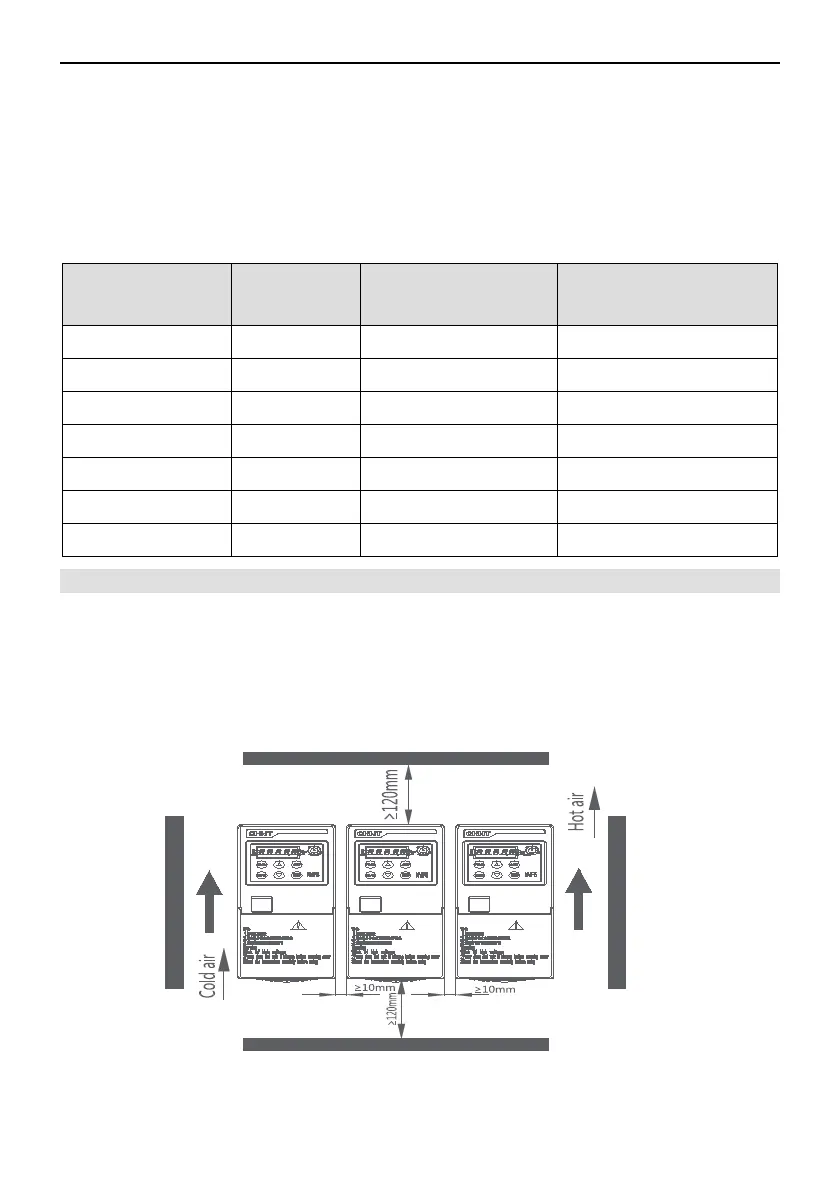
3.3 Installation
The inverter shall be installed at an indoor place ,good in ventilation and generally in a
vertical mode. When using inverter, please pay attention to installation distance
requirement.
The following are examples of multiple side-by-side installations and multiple
vertical installations.
(1)multiple side-by-side installations
Figure 3-3-1 Side-by-side Installatio Diagram
- 16 -