Installation FLEX-AUGER® Feed Delivery System
18
MA1032F
Bin Location
For easiest installation and most trouble-free operation, locate the feed bin directly in line with the FLEX-AUGER
System. The layout charts on Page 14 and Page 17 provide some points of reference for bin placement according
to the height at which the system enters the building. The 30 degree or straight-out boots combined with various
elbow hookups offer a wide range of possibilities. The charts are only for reference. Modify and adjust elbows
and tube sections as needed.
NOTE: Two 45 degree PVC elbows are standard with Model 108 FLEX-AUGER Delivery Systems. If additional
elbows are required they must be ordered separately.
The bin collar is installed during bin assembly. Chore-Time bins have a welded collar. Bin Adapter Kits are
available to modify existing bins so that the welded collar can be used. In addition, a Universal Adapter Plate is
available to allow the FLEX-AUGER boot to be installed to other manufacturers’ bins.
Tighten all bin-seal bolts from the nut side. This prevents cutting and "spinning out" of the plastic washer.
Boot Installation
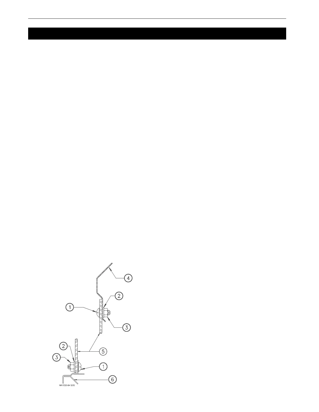
1.Insert the upper boot into the bin collar and turn it to line up with the direction that the auger line will go. The
boot must be as far up into the opening as it will go. Use the holes in the ring for drilling guides and drill 11/
32" (8.8 mm) holes in the upper rim of the boot. Attach the boot to the bin collar with the hardware provided.
(See Figure 1.)
IMPORTANT: Failure to install the hardware as shown in Figure 1 may cause breakage of the red
boot body.
2.Attach the transfer plate to the upper boot. Use truss head bin-seal bolts installed from the inside of the plate,
with flat washers placed under the nuts.
3.Insert the slide into the transfer plate slot so that it is in its operating position before bolting the slide shield in
place. Remove the paper backing from the sealing strip before fastening the slide shield to the transfer plate.
Use two 5/16-18 x 3/4" hex head machine screws to secure the shield.
4.Bolt the lower boot to the transfer plate using four 5/16-18x3/4" hex head machine screws.
5.After the auger tubes and auger have been installed, attach the 6197 Clean-Out Cover Plate or the optional
Proximity Boot Switch to the lower boot.
Installation
KEY DESCRIPTION PART NO.
1 5/16-18 X 3/4" Truss Hd. MS 7943-1
2 5/16" Nylon Washer 7946
3 5/16-18 Nylon Hex Nut 7945
4 Hopper Collar -
5 Boot Body -
6 Transfer Plate -
Figure 1.Boot Installation Diagram
 Loading...

