Installation FLEX-AUGER® Feed Delivery System
22
MA1032F
Supporting the System Inside the Building
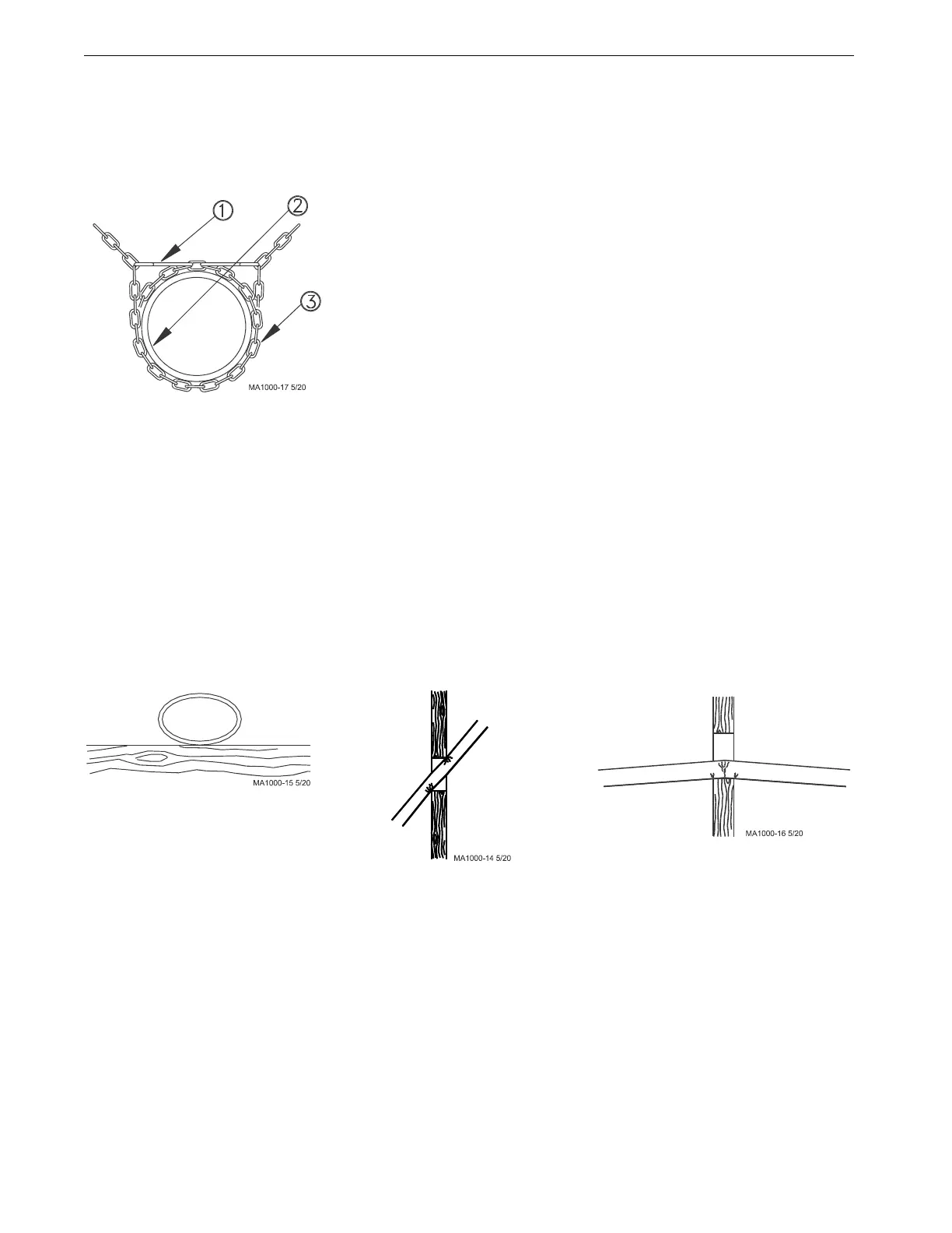
Support the auger tubing with chain and "S" hooks every 5 feet (1.5 m). Steel tube systems require support every
10 feet (3 m). The system should be restrained from swinging by using chain and "S" hooks to brace the auger
tube, as shown in Figure 6, every 20 feet (6 m). This is especially critical in UltraKARTM Feedkar applications
where hopper cars contact gate valves.
Horizontal elbows need to be supported in at least two places. Chain, screw hooks, and "S" hooks are supplied as
a suspension kit for supporting the equipment. Keep the line as level and straight as possible.
If Drop Feeders, Extension Hoppers, Outlet Drops with long angled Drop Tubes, or other loads are imposed on
the system, extra support will be required.
Power Units require extra support to resist the twisting encountered when the motor starts and stops. Use all of the
"ears" on the gearhead as well as the suspension point provided on the 6500 Control Unit Box to support the Power
Unit.
Adequate chain and "S" hooks are provided with each system to properly support it. Other means of supporting
the system are permissible as long as the system receives the correct support and the auger tube is not dented or
flattened.
When the auger tube passes through a side wall or partition, especially where it enters the building, the opening
should be made large enough so the auger tube can be supported without resting on the wall. If the auger tube rests
on the wall or partition, the auger tube may flatten out or become kinked--causing excessive wear. (See Figure 7.)
Key Description
1 “S” Hook
2 Auger Tube
3 Chain
Figure 6.Supporting the Auger Tubes
Auger tube kinked because
the supports are not high
enough to keep the weight of
the auger tube off the wall.
Tube pinched because auger tube
is not in line with hole in wall.
Auger tube flattened because
supports are too far away
from each side of the wall.
Figure 7.Incorrectly Supporting the Auger Tubes
 Loading...

