Installation FLEX-AUGER® Feed Delivery System
30
MA1032F
Feed Level Control Installation
The Hopper Level Control (or Drop Tube Switch) is installed in the feed hopper (or on the drop tube over the
feeder) at the power unit end of the line. This switch stops the FLEX-AUGER Feed Delivery System when the
last feeder is full. Install the hopper level control or drop tube switch according to instructions shipped with the
unit. Wire the switch into the system as specified in the appropriate wiring diagram in this manual.
Types of Boot Installations
Straight-Through Tandem Boot Installation
The Straight-Through Tandem Boots allow a single auger to remove feed from two separate feed bins. Feed should
only be drawn from one bin at a time.
Boot Baffles are required and included with the Straight-Out Boot Assembly.
Model 108 Straight-Through Tandem Systems do not use Feed Restrictors.
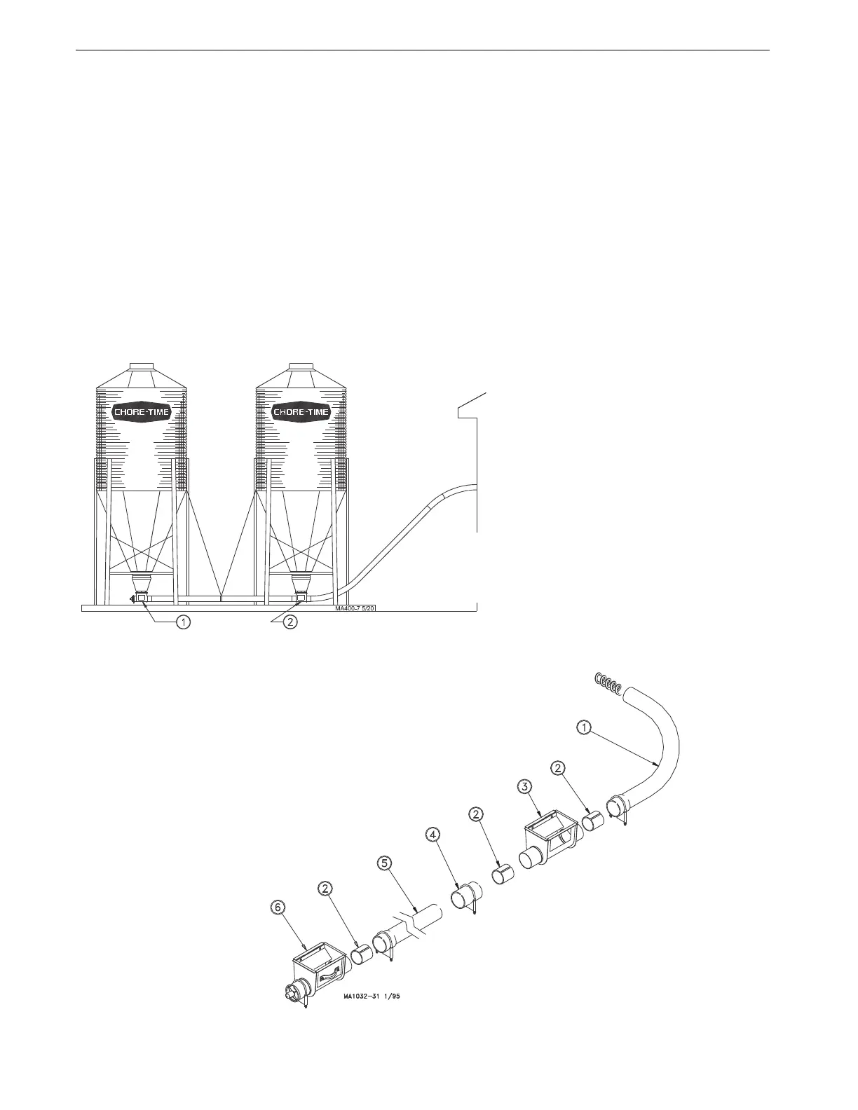
1.Install boots on both feed bins. Be sure the outlets on the boots are in line with the slotted tube anchors facing
in the direction the auger line will go. Figure 21 shows a typical Straight-Through Tandem System.
PVC Straight-Through Tandem
2.Place an Insert in the
belled end of the
connecting auger tube.
The Insert fits directly
over the outlet end of the
Terminal Boot.
Cut the straight end of the
auger tube even with the
stub tube on the
Intermediate Boot.
Slide an Insert into the end
of the auger tube and over
the inlet end of the
intermediate boot.
Secure this joint using a
Tube Coupler and clamp.
Place an Insert in the
belled end of the Elbow
before inserting over the
outlet end of the
Intermediate Boot.
Install tube clamps as
shown to secure the boot
components in place.
Key Description
1 Straight-Out Boot on Terminal Bin
2 Straight-Through Boot (w/Baffle)
on Intermediate Bin
Figure 21.Model 108 Straight-Through Tandem
Key Description
1PVC Elbow
2 Tube Insert
3 Straight-Thru Boot (Intermediate Bin)
4 Tube Connector
5 10’ (3 m) PVC Auger Tube
6 Straight-Out Boot (Terminal)
Figure 22.PVC Straight-Through Tandem
 Loading...

