FLEX-AUGER® Feed Delivery System Installation
23
MA1032F
Supporting the System Outside the Building
Some systems require additional support to avoid sagging auger tubes. This support must be adequate to support
the weight of the auger tubes filled with feed. Special attention should be given to avoid excessive pressure from
the auger being transferred to boot. Chain or cable suspended from the bin or building will not provide adequate
support for these systems.
Some common systems are shown in Figure 8 through Figure 12, with the recommended supports.
Note: Supports must be designed to prevent (weight) loads from being transferred back onto the boot.
REMEMBER: The auger tubes must be supported every 4-5 feet (1.2 to 1.5 m) for PVC systems and every 10
feet (3 m) for steel systems.
Screeners
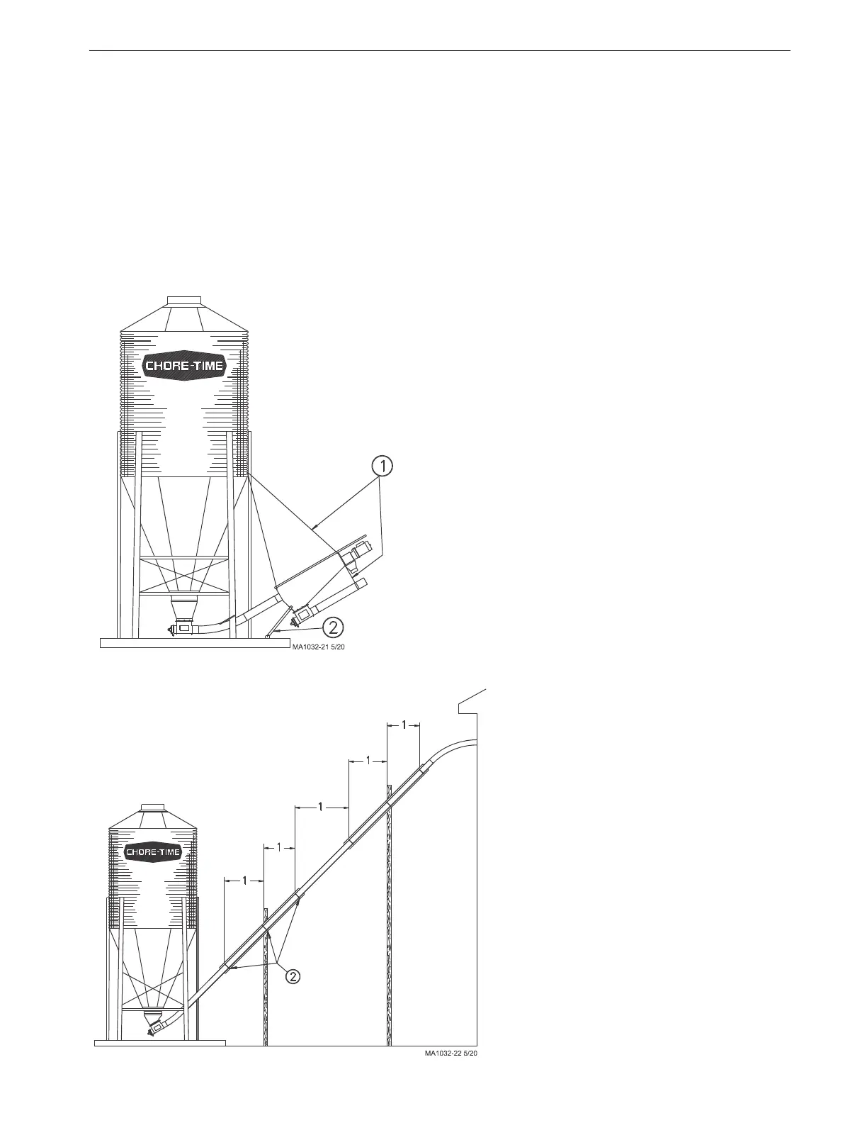
High Rise Auger Tube Support
Key Description
1 5’ (1.5 m) for PVC Systems
10’ (3 m) for Steel Systems
2 Screener Brace.
Figure 8.Screener Support
Key Description
1 5’ (1.5 m) for PVC Systems
10’ (3 m) for Steel Systems
2 Place clamps here.
Figure 9.High Rise Auger Tube Support
 Loading...

