Installation FLEX-AUGER® Feed Delivery System
26
MA1032F
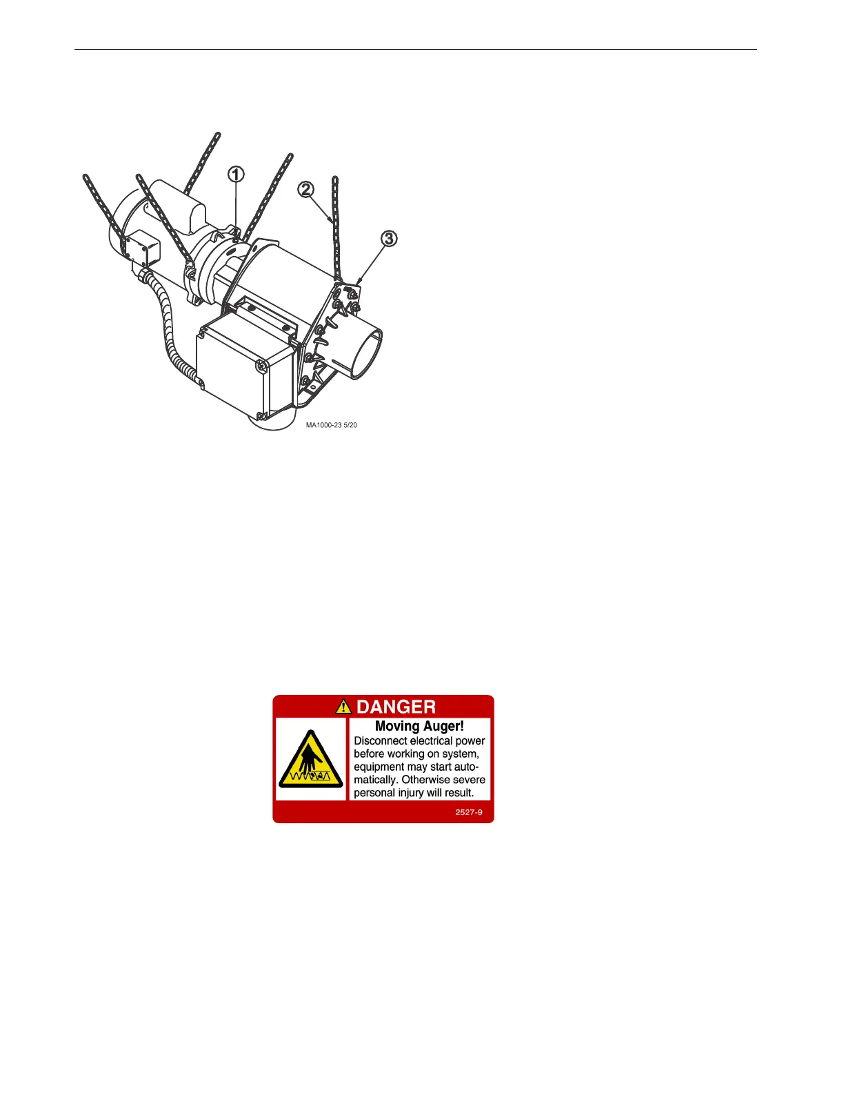
5.Support the Power Unit and Control Unit securely. Points are provided at the gearhead and the tube anchor
for hanging the equipment from the rafters with chain and "S" hooks supplied with the delivery system. (See
Figure 14.)
NOTE: Other ways of supporting the delivery system can be used where it is practical, as long as the supports
do not allow the equipment sag or do not make flat spots in the auger tubes.
6.Install the Driver Assembly on the power unit shaft. Start the socket headed screws but leave the anchor
block loose enough to slip the auger into it.
7.Replace the plastic shipping plug in the gearhead with the vent plug provided. Discard the Plastic Shipping
Plug.
NOTE: Unit must be protected from the elements. Unit as installed is not protected from direct rain or snow.
Belt Drive Control Unit Installation
The Belt Drive Control Unit installation is much the same as the direct drive unit. Mount the Belt Drive Adapter
and Motor to the control unit, then proceed with installation to the auger tube as described in this manual. Page 26
can be used as an assembly guide for the Belt Drive Control Unit.
Auger Installation
Use extreme caution when
working with the auger. The
auger is under tension and may
spring causing injury. Always
wear protective clothing and
protective glasses when
working with the auger.
Handle the FLEX-AUGER carefully. Dropping the rolls of auger may cause the auger to kink. Do not install an
auger that has a sharp kink in it. The kink will cause the auger to wear a hole in the tube at that spot. If the kink
cannot be straightened with pliers, the kink must be cut out and the auger brazed back together. Refer to the "Auger
Brazing" section in this manual for the correct brazing procedure.
Figure 14.Control Unit & Power Unit Suspension
Key Description
1 Power Unit
2 5/16-18 Screws
3 Control Unit
4 Flexible Cable
5 Anti-Short Bushing
6 90 Degree Connector
7 Tube Anchor
 Loading...

