FLEX-AUGER® Feed Delivery System Installation
27
MA1032F
1.Beginning at the boot, push the auger into the auger tube through the rear of the boot until the auger reaches
the control unit end of the line.
Caution! Use extreme caution when pushing the auger into the auger tubes. Keep your hands away from the end
of the Boot to avoid injury.
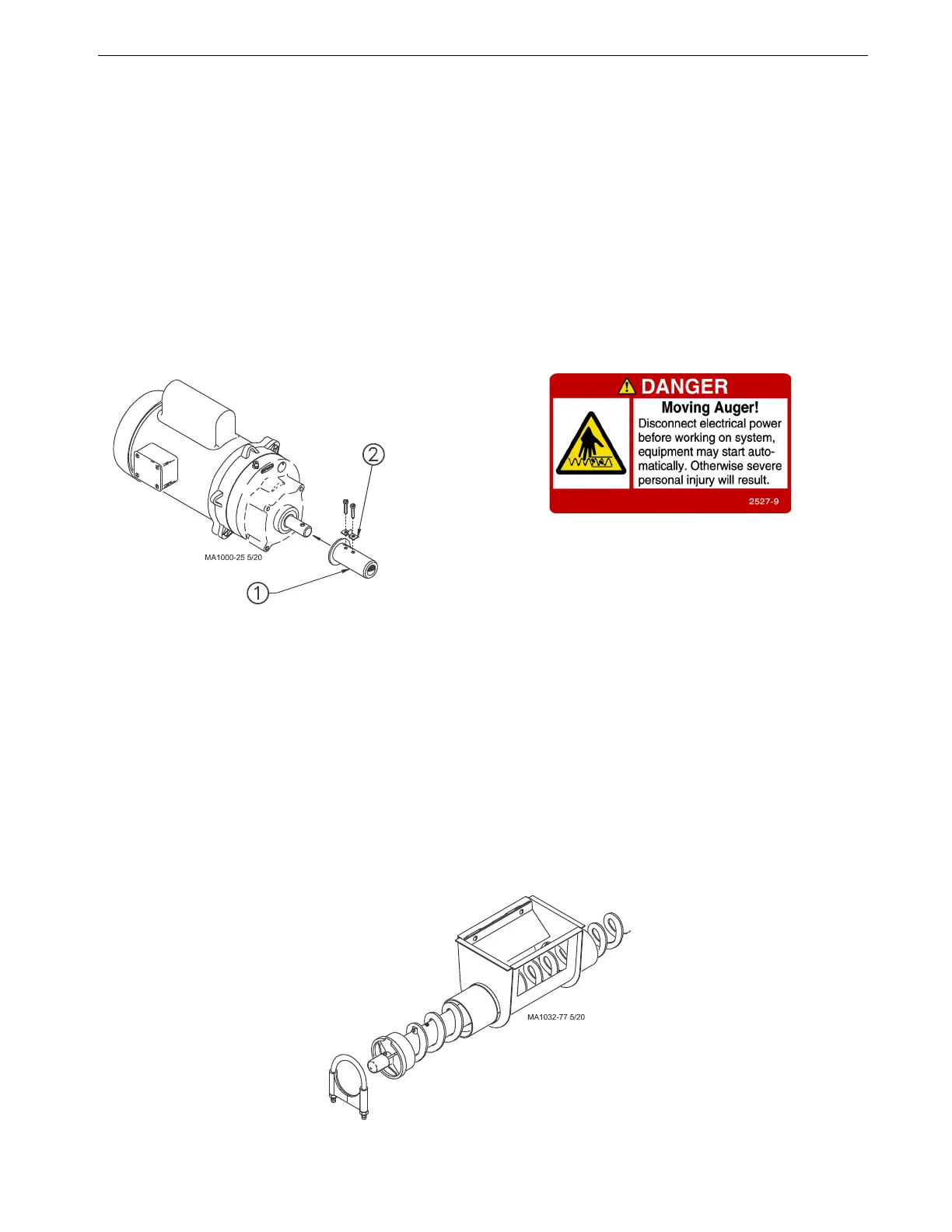
2.Attach the auger to the Driver Assembly by rotating the driver and threading the auger through the Anchor
Clamp.
3.Rotate the auger so that it is fully engaged on the Driver Assembly. Tighten the screws securely to clamp the
auger to the Driver Assembly. (See Figure 15.) Attach the drop tube and install the slide cover on the control
unit.
4.Pull on the loose end of the auger at the boot once or twice until it begins to stretch, then release it slowly.
This will bring the auger to its natural length.
Note: For ease of cutting, measure and mark the auger at the point where it is to be cut. Then, pull the auger an
additional 6-8" (150-200 mm) and use locking pliers to clamp the auger while you cut it.
IMPORTANT: Stretch the auger 8 inches (200 mm) for every 50 feet (15.2 m) of length. Example: For a 150 ft.
(45 m) system the auger should be cut 24 inches (610 mm) shorter than its natural length. Measure
the amount of stretch from the rear edge of the boot and cut the auger at that point.
5.Figure 16 shows the proper assembly of the Model 108 boot components. Insert the Anchor Shaft into the
auger until the auger touches the anchor flange. The auger must be threaded onto the Boot Anchor Assembly,
through the clamp pin. Use a 5/16" open-end wrench to tighten the clamp pin setscrew on the auger.
6.CAREFULLY remove the locking pliers while holding on to the Anchor and Bearing Assembly and auger
securely.
7.CAREFULLY allow auger to draw the Anchor and Bearing Assembly back into the Lower Boot. DO NOT
ALLOW THE BEARING TO BE SLAMMED BACK INTO THE BOOT.
8.Attach the Anchor and Bearing Assembly to the Boot, using tube clamp provided.
9.Place the cannonball in the boot.
Key Description
1 Model 108 Driver Assembly
2 Anchor Clamp
Figure 15.Model 108 Auger Installation
Figure 16.Model 108 Anchor and Bearing Installation
 Loading...

