Installation FLEX-AUGER® Feed Delivery System
20
MA1032F
Note: In some installations it may be possible to eliminate the elbow on the boot, using only a straight
auger tube and one elbow where the auger tube enters the building.
5.Dry-fit all parts. When satisfied that elbows and tubes fit together smoothly, glue with PVC cement
according to the instructions on cement container and/or on Page 49 of this manual.
6.ALL TUBE JOINTS EXPOSED TO MOISTURE AND WEATHER MUST BE SEALED OR CAULKED
TO WATERPROOF THEM IN ADDITION TO CEMENTING OR CLAMPING THE JOINT.
7.If there are more than 15 feet (4.5 meters) of auger tube between the boot and the building, provide
additional support for the tubes so that the boot does not carry the weight of the auger. Extra support can be
achieved with cables or chain fastened to the bin legs and the auger tube.
8.Locate and cut the outlet holes as required and specified in the instructions on Page 20.
9.Slide (2) Outlet Insert Rings onto the pipe at each outlet hole location.
Each Outlet Assembly is shipped with Insert Rings for both steel and PVC pipes.
The 3/8" (10 mm) thick rings are for steel tube systems. The 1/4" (6 mm) thick rings are for PVC tube
systems. Be sure to use the appropriate Insert Rings for your system.
10.Install the remaining tubes in the system.
The PVC auger tubes should be fastened together using PVC cement.
Model 108 Tube connectors should be used to connect steel auger tubes.
Outlet Drop Installation
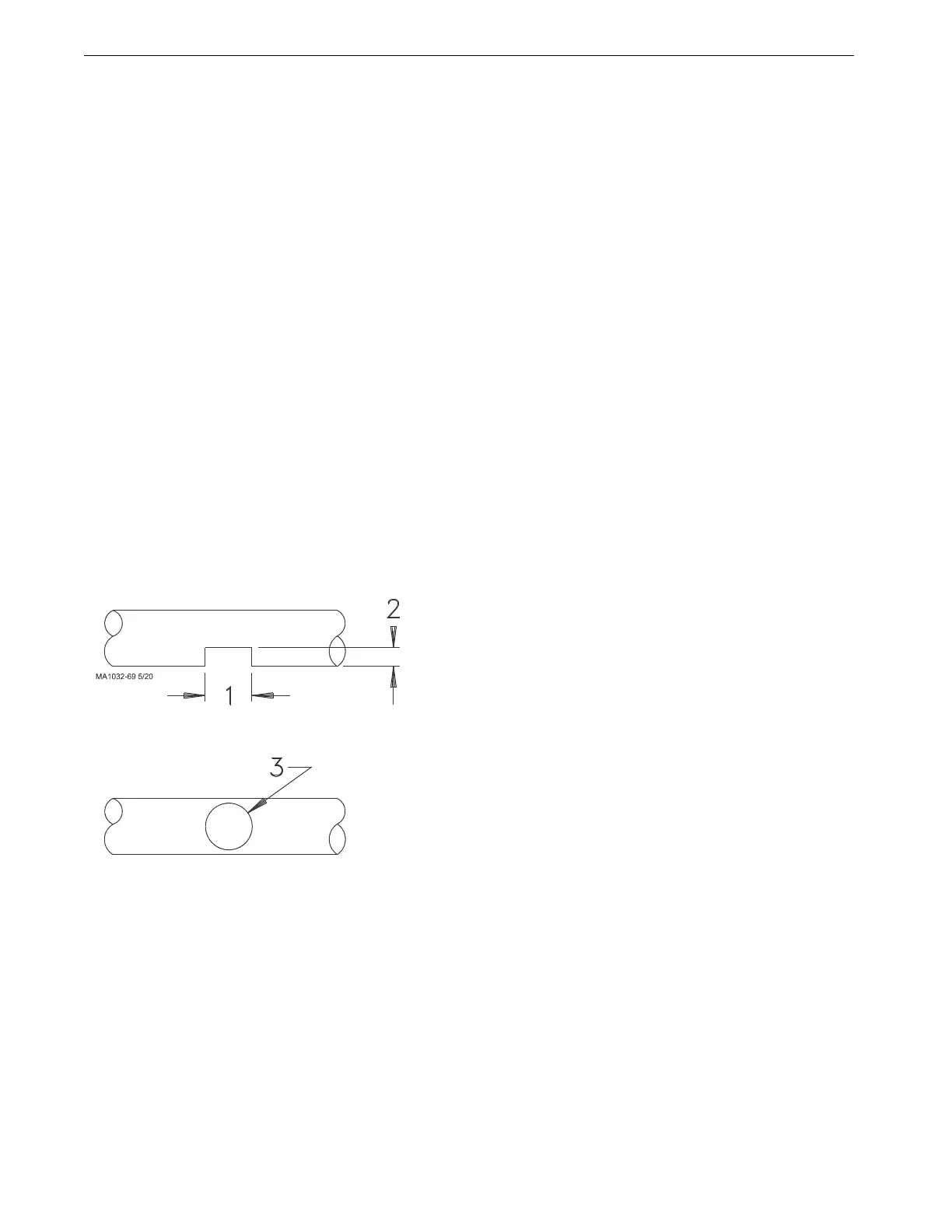
Cut the outlet hole in the auger tube. A sabre saw or hacksaw is handy for making the cuts when total feed dropout
is desired. (See Figure 4.) Use a file to remove burrs from opening.
Note: For total feed drop out, outlet holes should be 5-3/8" (137 mm). If some feed carry over is required, outlet
holes should be 3-1/2" (90 mm).
Key Description
1 5-3/8" (137 mm)
2 2" (50 mm)
3 3-1/2" (90 mm)
Figure 4.Outlet Holes provide total or partial feed dropout
 Loading...

