FLEX-AUGER® Feed Delivery System Installation
21
MA1032F
1.Wrap the rotary slide around the auger tube. POSITION SLIDES IN SAME DIRECTION FOR ALL
DROPS SO THAT THE SLIDES WILL ALL OPERATE THE SAME WHEN ROPES ARE PULLED.
2.Thread the rope through the ends of the rotary slide.
3.Tie the ends of the rotary slide together so that the ends of the rope are the same length.
4.Open rope guide holes molded into the drop halves. Use a 3/16" (5 mm) drill bit and power drill to make a
good hole for the rope.
NOTE: DO NOT OPEN THESE HOLES IF THE ROTARY SLIDE WILL NOT BE INSTALLED.
5.Thread the rope ends through the guide holes in the drop halves.
6.Position drop halves over the rotary slide and fasten the two halves together using hardware provided. (See
Figure 5.)
Insert Rings are provided for both Steel Systems (Thicker Rings) and PVC Systems (Thinner Rings).
Slide the Insert Rings (with Flanges out) into position between the outlet halves to serve as spacers.
7.Test the operation of the rotary slide by pulling on the ends of the rope. Be sure the outlet drop is centered
over the outlet hole, then move the rotary slide to the open position (check by looking up through the drop
opening) and mark the short end of the rope where it goes through the guide hole.
Tie a knot in the rope at the marked spot to act as a stop for the rotary slide.
8.Install green and red indicator balls on the ends of the rope. Tie knots in the rope to hold the balls in place.
Use the green ball on the rope used to open the outlet drop. Use the red ball on the rope used to close the
drop. This will indicate if the Outlet Drop is open or closed.
9.Dab PVC cement around the auger tube to prevent the drop from shifting on the tube.
10.Two screws are supplied for use in the bottom of the drop to attach a drop tube to the system.
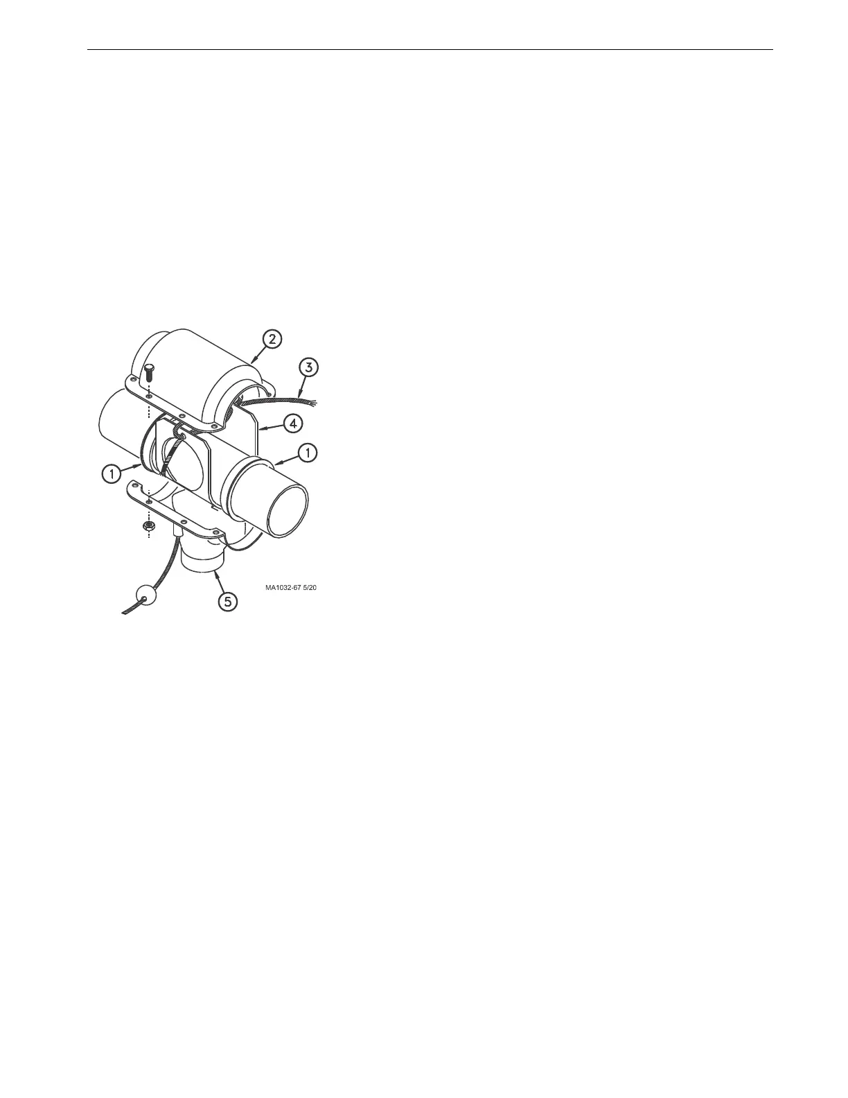
Figure 5.Model 108 Outlet Drop Assembly
Key Description
1 Insert (For Steel or PVC System)
2 Top Half
3Rope
4 Rotary Slide
5 Bottom Half w/Spout
 Loading...

