Wiring Chore-Tronics® 3 Breeder Edition Control
36
MT2484A
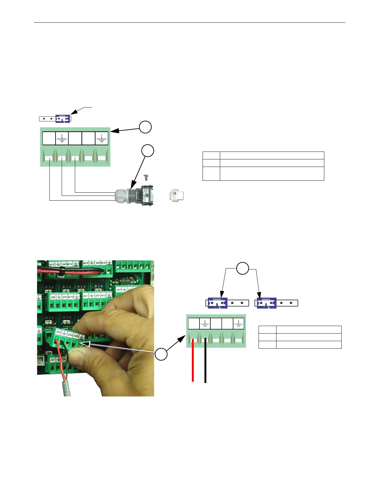
Relative Humidity Sensor (RH) Wiring
The optional Relative Humidity Sensor (Item 1) requires a three-conductor wire to connect the sensor to the
Chore-Tronics
®
3 I/O board. The Sensor is connected to one of the Analog (AI) Inputs on the IO board.
Terminal #1 on the relative humidity sensor is connected to the +24 v terminal on the IO board (see
diagram). This is the same +24 v terminal used by the Static Pressure Sensor. Terminal #2 on the Relative
Humidity Sensor is connected to the Analog Input (AI) terminal of the analog Input being used (See Figure
25). Terminal #3 is connected to the ground terminal of the Analog Input (AI) being used. Make sure that
the Blue Jumper above the Analog Input that the RH sensor is connected to is set to "U".
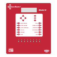
Temperature Sensor Wiring
Temperature Sensor wires can be connected to any one of the Analog Inputs (AI1 through AI16) of the I/O
board. Whatever AI Inputs the Temperature Sensors are connected to, make sure that the blue jumper above
each Input is set to "R" as shown. There are no polarity restrictions for the Temperature Sensors.
Item Description
1 Relative Humidity Sensor Quick Connect
2 I/O Board Analog Input (AI) Terminal of
your Choice
2
1
Blue Jumper in the "U" position
Item Description
1 Analog Input (AI5)
2 blue jumper set to "R"
Black
Red
2
1