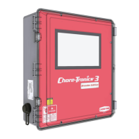
Chore-Tronics® 3 Breeder Edition Control Control Setup
MT2484A
9
BinTrac to Chore-Tronics Control Calibration
For calibrating the HouseLink HL-10P/HL-10P(LV) with
Chore-Tronic's® 3 control, please refer to these instructions.
1.Install the load cell system per BinTrac’s Installation
Manual.
2.Connect the Chore-tronics
®
3 to BinTrac. See “BinTrac
to Chore-Tronics Control Wiring” on page 32.
3.Setup the analog input in the CT 3. From the drop in the
Board column select the device. The last number in the
device name is the address that you assigned to the ILM
(SJB).
BinTrac Load Cell Calibration
1.The BinTrac House Link HL-10P(LV) has four dip
switches that need to be set up for configuration.
2.The settings on the switches S1 and S2 coincide with the
bin: Set for Bin B.
3.Set S3 to the ON position to allow the ZERO to be tracked by the house controls.
4.Set S4 to the ON position to provide a 2mV/V at full scale instead.
5.Bin D must be enabled on the Bin Trac Indicator when BinTrac Monitor is connected to: BinTrac HouseLink
HL-10P/HL-10P(LV).
6.Refer to the BinTrac Installation and Operation Manual HouseLINK HL-10P & HL-10P(LV) on how to make
these settings.
7.Once the unit is wired and the dip switches are set up correctly, you can now start the Calibration.
8.Two people are needed for this procedure. One at the BinTrac HouseLINK HL-10P & HL-10P(LV) box and
one at the CT 3 control.
9.On the board of the HouseLINK HL-10P
& HL-10P(LV) there is a Test button that
will be used to send a Zero and Full bin
calibration number.
BinTrac HouseLink HL-10P
ON
123 42
Bin S1 S2 S3 S4
DOnOnOffOff
Bin S1 S2 S3 S4
A Off Off Off Off
Bin S1 S2 S3 S4
B On Off Off Off
ON
123 42
Bin S1 S2 S3 S4
C Off On Off Off
ON
123 42
ON
123 42
Bin-Trac Dip Switch Settings

 Loading...