Description of ZERO Correction
6-1
6. Description of ZERO Correction
1. Power on the instrument after all are normal, enter main index as the below screen
shown.
E A S . D I S P L A Y >
*
D R I V E : P U L S E +
D R Y : O
F
F
T R I G . : I N T
N E X T P A G E 1
← Select DRY CIRCUIT OFF or ON
← Switch to next page (Now is page 1)
2. Press [F4] to enter the screen as below shown.
E A S . D I S P L A Y >
*
R A N G E : A 2 0 0
S P E E D : F A S T
Z E R O : O F F
N E X T P A G E 2
← Select zero function OFF or ON
← Switch to next page (Now is page 2)
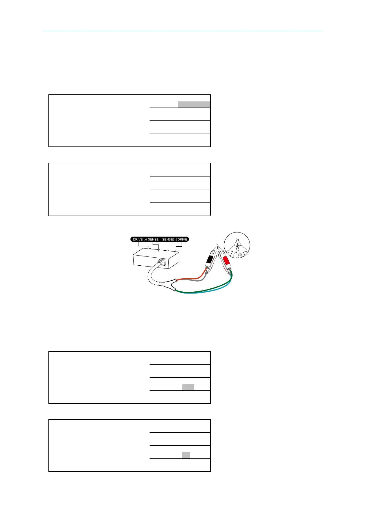
3. Deduct the residual impedance from test fixture or test cable.
The figure shown above is for telling users to do test cable zero at present. Be aware that
connection is for connecting H
CUR
and L
CUR
after the test cable is connected as above figure.
Next, the connection of
POT
and
CUR,
please prepare the test cable and press [F3] for the
screen turning into ON that test cable zero action is already processed.
For example:
E A S . D I S P L A Y >
*
R A N G E : A 2 0
Ω
S P E E D : S L O W
Z E R O : O F F
N E X T P A G E 2
← Select zero function OFF
The screen is shown as below after [F3] is pressed.
E A S . D I S P L A Y >
*
R A N G E : A 2 0
Ω
S P E E D : S L O W
Z E R O : O N
N E X T P A G E 2
← Select zero function ON