Description of Handler Interface
7-1
7. Description of Handler Interface
BINNING and COMPARE in 16502 are all connected to external unit by Handler interface.
The connectors are 24 Pin, pin descriptions are as following.
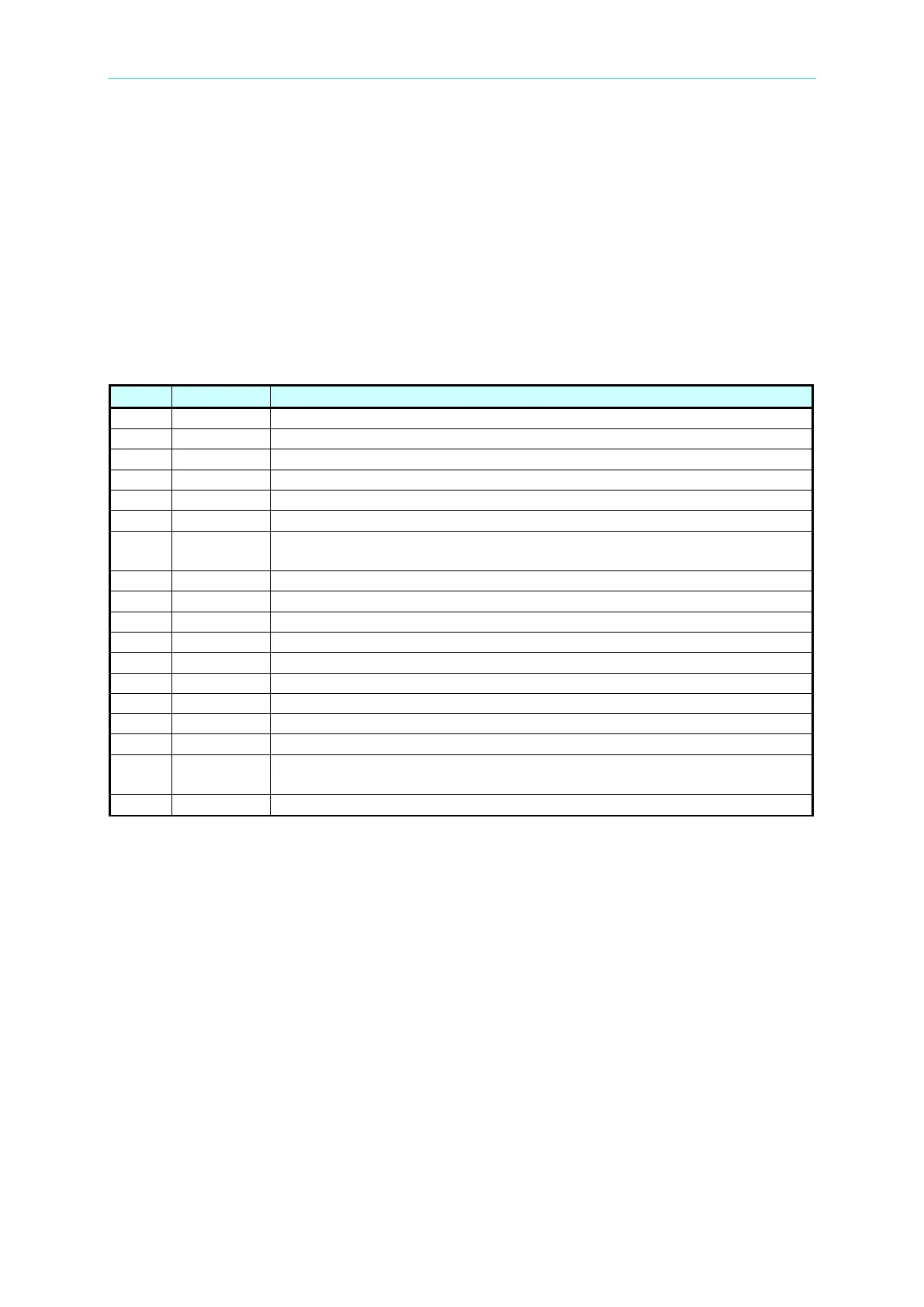
7.1 Description of Handler Interface Pins for
BINNING
BIN 7, primary parameter test value of Rx is within BIN 7 setting range
BIN 8, primary parameter test value of Rx is within BIN 8 setting range
Ground the internal power source
9,13,15
BIN OUT
BIN OUT, primary parameter test value of Rx is not in all setting
specifications
External DC voltage, acceptable range is +5V~24V
BIN 5, primary parameter test value of Rx is within BIN 5 setting range
BIN 6, primary parameter test value of Rx is within BIN 6 setting range
BIN 1, primary parameter test value of Rx is within BIN 1 setting range
BIN 2, primary parameter test value of Rx is within BIN 2 setting range
BIN 3, primary parameter test value of Rx is within BIN 3 setting range
22 /ACQ
End of the analog sampling. It is able to shift the next DUT to the
16502 test terminal.
BIN 4, primary parameter test value of Rx is within BIN 4 setting range