Description of Panel
4-3
(3) Power Voltage Switch
Ensure power is off, then use screwdriver to switch to required voltage.
(4) IEEE-488 INTERFACE Socket (Option)
According to IEEE488-1978 standard input/output cord. The functions are: total remote
control, output selection result, with or without controller, receives IEEE-488 interface
connection line.
(5) TC SENSE Socket (Option)
The connection socket of temperature probe is mainly for temperature measuring.
(6) HANDLER INTERFACE Socket (Option)
To component controller, output is GO/NG status etc., input is “Start” signal. Receive
Amphonol "Microribbon" plug P/N 57-30240 or equivalent object.
(7) RS-232 SERIES PORT
Standard RS-232 interface.
4.3 Setting for Operation
4.3.1 Setting the System Parameters (System Setup)
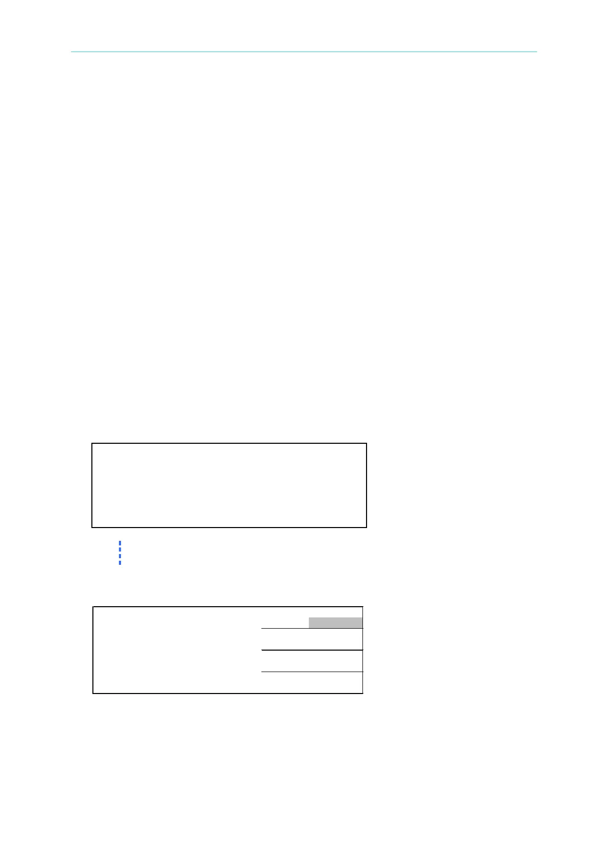
1. Power on the meter and the LCD will prompt the company name, its phone and fax
number as well as the model number of this instrument along with the firmware version as
shown below:
©
A R . 2 0 0 2 V E R : 2 . 0 0 1 6 / 1 2 / 0 3
Press [System Setup] and [] at any time can show this screen when the meter
is powered on.
2. The meter will run self test after powered on for 1 second, and then it will enter the
following measurement screen:
E A S . D I S P L A Y >
*
D R I V E : P U L S E +
D R Y : O
F
F
T R I G . : I N T
N E X T P A G E 1
3. To set the system parameters, press [System Setup] after powered on. It will enter the
following screen: