Electrical Safety Analyzer 19032-P Quick Start Guide
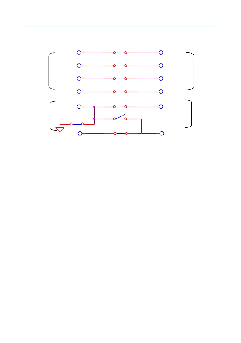
rear panel are short-circuited as Figure 4-15 shown.
37
1
RL2
1 2
RL3
1 2
RL4
1 2
RL6
1 2
RL5
1 2
RL7
1 2
DRIVE+
SENSE+ SENSE+
SENSE-SENSE-
DRIVE-
HV2HV2
DRIVE-
DRIVE+
RL1
HV1
HV1
1 2
RL8
1 2
High voltage
output on
rear panel
High voltage
output on
front panel
GB output
on front
panel
GB output
on rear
panel
Figure 4-15
(b) End test: HV1 terminal on front panel and that on rear panel are
also short-circuited. When [STOP] key is pressed, HV1 terminal
on front panel and that on rear panel are open-circuited.
(2) When set CHANNEL 3 as L (low):
(a) Start test: HV1 terminal on rear panel and HV2 on front panel are
short-circuited with low voltage terminal. DRIVE, SENSE
terminals on front panel and DRIVE, SENSE terminals on rear
panel are open-circuited as below Figure 4-16 shown.

 Loading...

