19
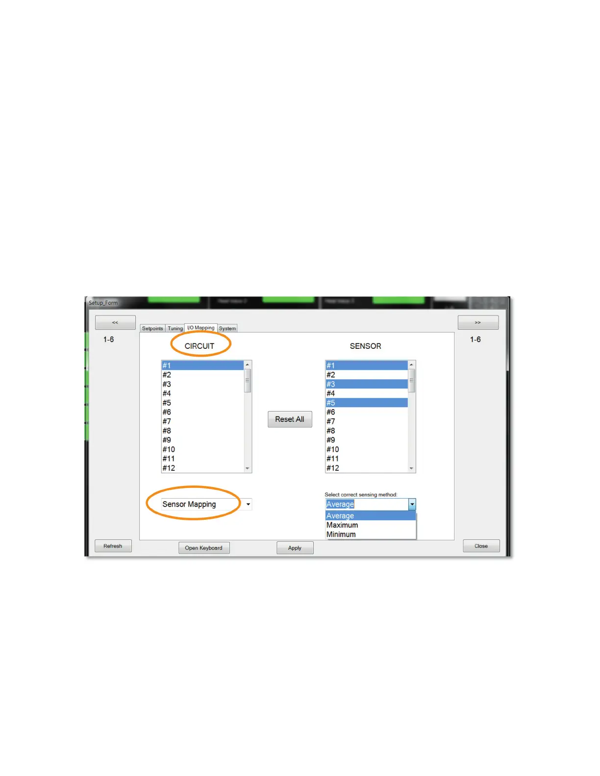
Multiple Sensor Mapping
A single sensor may be used independently or combined with other sensors to control more than one circuit.
For Example:
The average temperature of Sensors 1, 3 & 5 is used to control Circuit 1 while simultaneously the maximum
Temperature of Sensor 3, 4 & 5 is used to control Circuit 2.
Combining Sensing Types
The owner may need to have multiple Line and/or Ambient Sensing control scenarios occurring simultaneously.
For example, these may be occurring simultaneously:
1) Circuits 1, 2, 3, 4, & 5 are all controlled by a single RTD (Sensor 1) that is sensing the ambient tempera-
ture (Ambient Sensing)
2) Circuit 6 is controlled by Sensor input 2 which is strapped to a process pipe. (Line Sensing)
Sensor Mapping is accomplished within the I/O Mapping Tab found in the Setup Property Sheet. See Figure 14.
Figure 14
 Loading...


