© CIAS Elettronica S.r.l. Ed. 1.2
Installation Manual Page 35 of 47 MICRO-RAY
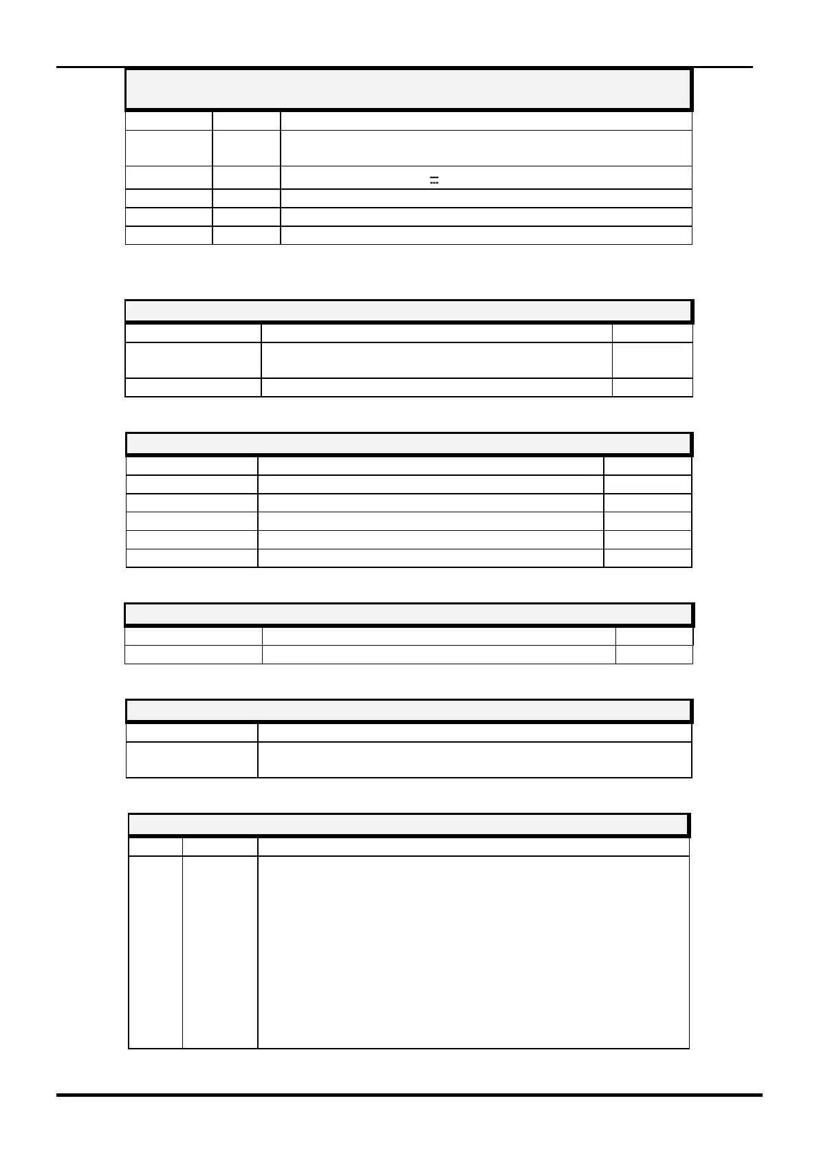
CONNECTOR J1
10 pin connector for local PC connection
Note 1: Use only for ray 1, do not connect for the rays 2, 3, 4.
Serial Line Termination (Jp1 position 1/2 =
termination NOT inserted)
Not used (keep in position 1/2)
Alignment and Adjustment Functions
Alignment and Adjustment Functions
ALIGNMENT / ADJUSTMENTS CONFIRMATION BUTTON
Activation / writing confirmation / alignment / adjustment
acquisition phase
Position 0 = Normal Functionality
Position 1 = Barrier Alignment
Position 2 = Channel acquisition and field value
Position 3 = Selection of the type of application
Position 4 = Walk-Test
Position 5 = Environmental noise filter setting
and ray interruption time
Position 6 = Anti-masking values setting
Position 7 = Not active
Position 8 = Read/write Barrier Number
Position 9 = Not active