EasyManua.ls Logo

cias MICRO-RAY - Terminal Blocks, Connectors and Functionality of the RX Circuit

cias MICRO-RAY
Print Icon
To Next Page IconTo Next Page
To Previous Page IconTo Previous Page
Loading...
© CIAS Elettronica S.r.l. Ed. 1.2
Installation Manual Page 34 of 47 MICRO-RAY
BUTTON
Symbol
Function
S1
Board Reset Button
Terminal blocks, Connectors and Functionality of the RX circuit
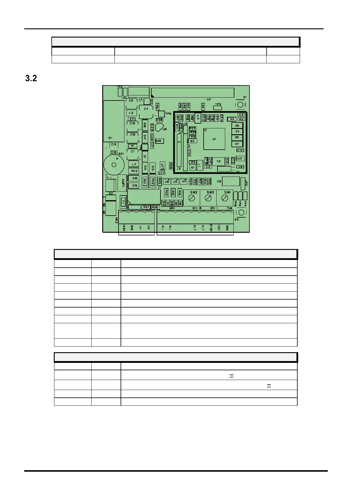
Figure 12 Topographic arrangement of the components in the circuit
TERMINAL BLOCK MS1
Term.Block
Symbol
Function
1
ALL 1
Alarm Relay Contact (C)
2
ALL 2
Alarm Relay Contact (NC)
3
TMP
Tamper Relay Contact (C) - Note 1
4
TMP
Tamper Relay Contact (NC) - Note 1
5
FLT
Fault Relay Contact (C)
6
FLT
Fault Relay Contact (NC)
7
STBY
Tamper Column Input (Norm. Closed to GND)
8
TEST
Power Presence Input (Norm. Closed to GND)
(Open when not used) - Note 1
9
GND
Reference potential for Tamper and Power Presence
TERMINAL BLOCK MS2
Term.Block
Symbol
Function
1
13.8V
Positive Power supply Input (+13.8 V )
2
GND
Negative Input for power Supply and for Data (0 V )
3
LH
+ RS 485 High Data Line
4
LO
- RS 485 Low Data Line
1
TMP
TMP

Table of Contents

Related product manuals