© CIAS Elettronica S.r.l. Ed. 1.2
Installation Manual Page 36 of 47 MICRO-RAY
PARAMETER READING / WRITING SELECTORS AND INDIVIDUAL
BEAM DIRECTION
Decimal switch for reading or setting parameters during the
alignment phases (tens)
Decimal switch for reading or setting parameters during the
alignment phases (units)
MEASUREMENT POINTS OF THE RECEIVER
Negative for Measure (GND)
Voltage of the automatic gain control AGC
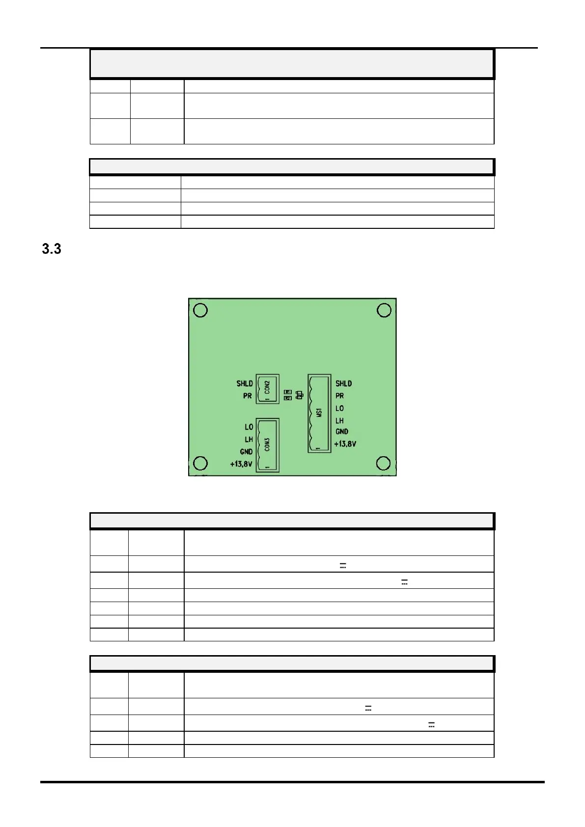
Terminal blocks, of the MICRO-RAY Interface circuit
The MICRO-RAY modules are all pre-wired in the factory and connected to the MS1 terminal of
the interface circuit (positioned approximately in the middle of the column).
Figure 13 Topographical arrangement of the components in the circuit
TERMINAL BLOCK MS1 CONNECTION TO MICRO-RAY
Positive Power Supply (+13.8 V )
Negative for Power Supply and for Data (0 V )
Power Presence (Norm. to GND)
Positive Power supply Input (+13.8 V )
Negative Input for Power Supply and for Data (0 V )