© CIAS Elettronica S.r.l. Ed. 1.2
Installation Manual Page 32 of 47 MICRO-RAY
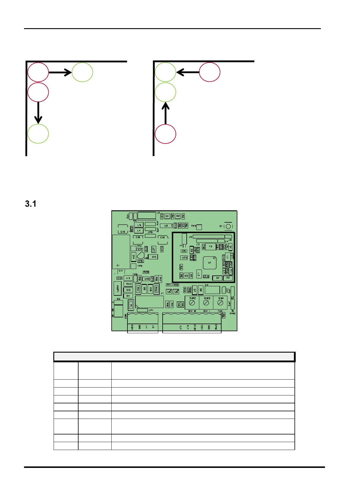
Corners
The positioning in the corners is carried out side by side by placing the type A or type B columns
as shown in figure 10.
Figure 10
3 CONNECTIONS
Terminal blocks, Connectors and Functionality of the TX circuit
Figure 11 Topographical arrangement of the components in the circuit
Tamper Relay Contact (C) - Note 1
Tamper Relay Contact (NC) - Note 1
Tamper Column Input (Norm. Closed to GND)
Power Presence Input (Norm. Closed to GND)
(Open when not used) - Note 1
Reference potential for Tamper and Power Presence