© CIAS Elettronica S.r.l. Ed. 1.2
Installation Manual Page 31 of 47 MICRO-RAY
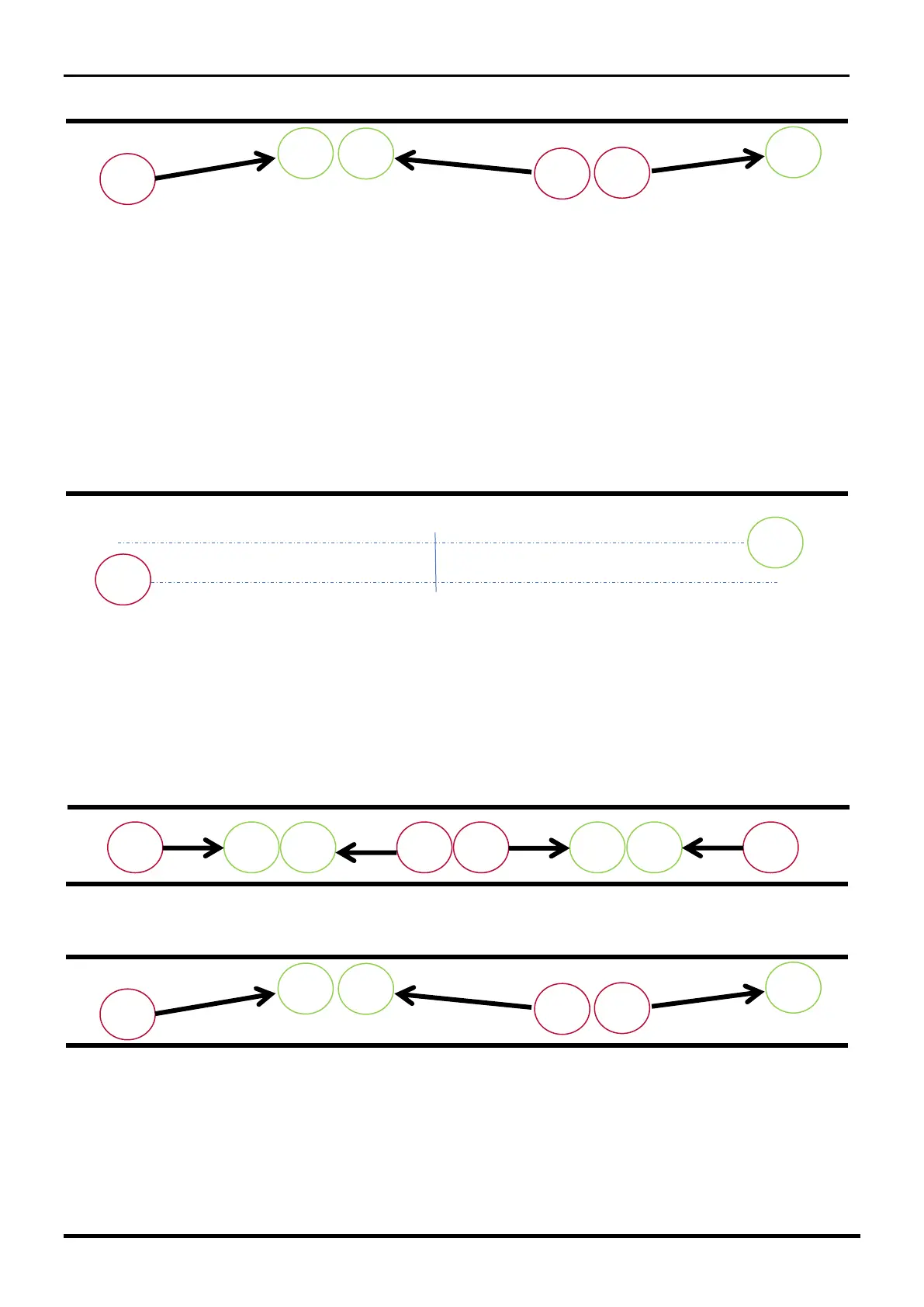
Figure 8b
Note: Do not place the columns at a distance less than 50cm from the fence or 35cm from
the wall. (These distances are referred to from the center of antenna).
Warning: With PARALLEL installation (fig. 8a), in some exceptional cases (normally
dependent on the type of fence or wall), the barrier placed at a distance ranging from 90cm
to 160cm from the wall/fence could be subject to phenomena that make a difficult alignment
of the rays positioned at middle height. In these cases, it is preferable to use the
DIAGONAL installation mode (fig 8b) or dislocating the columns by 1m (fig. 8c).
Figure 8c
Installation between walls/fences
In the case of installation in corridors placed between two fences or walls or between fence and
wall you must follow the same indications shown above. See figures 9a and 9b.
Figure 9a
Figure 9b