EN7510364-00
EN - 8
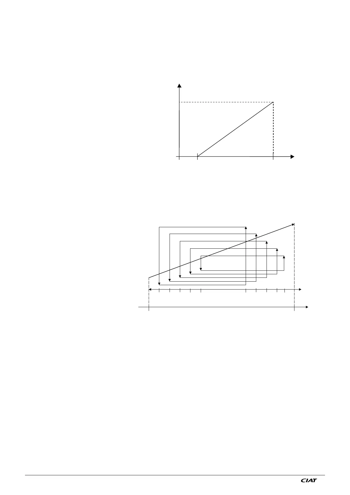
4.1.3 Mixed control 1
Used for variable speed control on stage 1. The other fan stages are controlled in series according to the stage 1 control signal
(0/10 V) which corresponds to the fan speed (0/100%).
The diagram below illustrates this type of control:
4.1.2 Speed control
Used to control the speed of all fans with EC motors.
● The board sends a 0-10V signal to control the EC.
● The following diagram illustrates the output signal according to the measurement taken on the fluid (temperature or pressure)
and the setpoint.
1 0/10V output signal for 1 FMA line units and/or 1 circuit
units.
2 0/10V output signal for 2 FMA line units and/or 2 circuit
units.
Stage operation:
Stage control is defined according to a percentage
of the operating range of the 1st stage.
7 stages:
5-15-25-30-40-45% and 50-55-65-75-85-95%
6 stages:
5-15-25-35-45% and 55-65-75-85-95%
(see example)
5 stages:
10-20-30-40% and 60-70-80-90%
4 stages:
10-25-40% and 60-75-90% for stages 2-3-4
3 stages:
15-30% and 70-85% for stages 2-3
2 stages:
20 and 80% for stage 2
EXAMPLE FOR CIRCUIT 1, COIL 1
5,5V
6,5V
7,5V
A121
A121 + A150
0,5V
1,5V
2,5V
3,5
4,5V
8,5V
9,5V
V
2nd stage
3rd stage
4th stage
5th stage
6th stage
Measurement
Fan control
signal
(Setpoint)
The diagram illustrates this operating mode for a system with 6 control stages The diagram illustrates this operating mode for a
system with 6 control stages
0V
10V
EXAMPLE COIL 1, CIRCUIT 1, SETPOINT 1
Voltage
Measurement
(A150 = hysteresis)