EN
EN - 9
EN7510364-00
ΔΔ
Δ
%
0 %
Δ
Stage Stage Stage Stage Stage
Measurement
Setpoint +
Stage 1
hysteresis
Setpoint
Hysteresis Stage 6
Hysteresis Stage 5
Hysteresis Stage 4
Hysteresis Stage 3
Hysteresis Stage 2
STAGE no.6
STAGE no.5
STAGE no.4
STAGE no.3
STAGE no.2
STAGE no.1
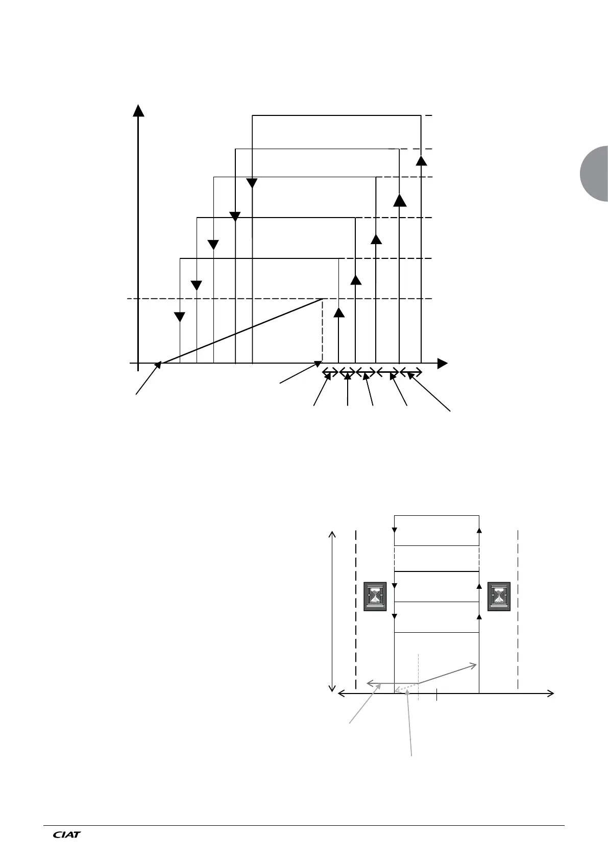
4.1.4 Mixed control 2
Used for variable speed control on stage 1.
The other fan stages are controlled in series when the 1st stage is at 100%.
The following diagram illustrates this operating mode for a system with 6 control stages.
● Regulation of floors On/Off (AC fans):
- If the fluid temperature> A121 + A106 and when
the temperature continues to rise for> A107
regulation put into operation an additional control
stage.
- If the fluid temperature <A121-A106 and when the
temperature continues to drop for a period <A108
the control, cut a regulation stage
- If the fluid temperature (measured) is between
A121 - A106 and A121 + A106, there is no action
on the stage of AC fans.
The diagram illustrates this operating mode for a device
with 7 stages of regulation
A108 A107
A121 ou A122
A115
A121 + A106
A121 – A106
If no stage AC
If stage AC
CONTROL STAGE
Stage no 7 AC
Stage no 3 AC
Stage no 2 AC
Stage no 1
Temp
outside
range
Temp
outside
range
Measurement
Setpoint
4.1.5 Mixed control 3
The stage no 1 (EC) is is always the first lit floor and the switched top floor off.
The other floors, of the fan (AC) light up depending on the A110 setting.