EN
EN - 33
EN7510364-00
MACHINE PARAMETERS
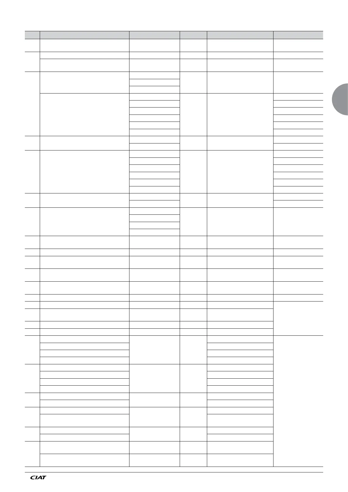
No. Description Adjustment possible By default Display conditions Notes
A01 UNIT TYPE
FLATBED COILS
V COIL
FLATBED
COILS
A02
NUMBER OF COILS 1 or 2 1 If A01 = Flat
PARALLEL COILS
YES (if 1 circuit)
NO (if 2 circuit)
YES If A01 = V
Parallel (on Vextra) =
Same fluid as in the 2 coils
A03
COIL TYPE
1 LT water circuit
1 LT water
circuit
If A02 = 1 or A02 = YES
LT: Low temperature <
= 95°C
HT: High temperature > 95
1 HT water circuit
1 refrig. circuit
COIL 1 TYPE
1 LT water circuit
1 LT water
circuit
If A01 = Flat or A02 = NO
2 LT water circuits
1 HT water circuit
2 HT water circuits
1 refrig. circuit
2 refrig. circuits
A04 COIL 1 CIRCUIT
BALANCED
BALANCED If A01 = Flat and A03 = 2 circuits
NON BALANCED
A05 COIL 2 TYPE
1 LT water circuit
1 LT water
circuit
If A02 = 2 or A02 = NO
2 LT water circuits
1 HT water circuit
2 HT water circuits
1 refrig. circuit
2 refrig. circuits
A6 COIL 2 CIRCUIT
BALANCED
BALANCED If A01 = Flat and A05 = 2 circuits
NON BALANCED
A07 CONTROL TYPE
ON/OFF
ON/OFF See section 4.1
Variable speed
Mixed 1
Mixed 2
A08 NUMBER OF FAN STAGES 1-2-3-4-5-6-7 2
If 2 refrig. circuits max 6
stages and 2 lines
A09 NUMBER OF FAN LINES 1 or 2 1 If A01 = Flat and A03 = 2 or A05 = 2
No display and adjustment
possible A09 = 1
If A01 Flat and A03 = 1 and A05 = 1
No display and adjustment
possible A09 = 1
If A02 = YES
No display and adjustment
possible A09 = 2
If A02 = NO
A10 MISTING Yes and No No
A15.1 ELECTRICAL QUANTITY MEASUREMENT Yes and No No
Visible if energy meter
option
A15.2 TYPE OF NET ELECTRICAL GRID
1BL-2BL-3BL-4BL-3NBL-
4NBL
3BL
A16 PRIMARY CT RATING 5 to 1000 (resolution: 1) 5A If A15.1 = YES
A17 SECONDARY CT RATING None 5A If A15.1 = YES
A30
TOP OF SENSOR RANGE
10 to 50 b (increments
of 0.1)
34
If A02 = 1 and A03 = 1 refrig. circuit
For condensers only
TOP OF COIL1 SENSOR RANGE If A02 = 2 and A033 = 1 refrig. circuit
TOP OF CIRCUIT 1 SENSOR RANGE If A02 = 1 and A03 = 2 refrig. circuit
TOP OF CIRCUIT1 COIL1 SENSOR RANGE If A02 = 2 and A03 = 2 refrig. circuit
A31
BOTTOM OF SENSOR RANGE
-1 to 10 bar (increments
of 0.1)
-0.5
If A02 = 1 and A03 = 1 refrig. circuit
BOTTOM OF COIL 1 SENSOR RANGE If A02 = 2 and A03 = 1 refrig. circuit
BOTTOM OF CIRCUIT 1 SENSOR RANGE If A02 = 1 and A03 = 2 refrig. circuit
BOTTOM OF CIRCUIT1 COIL1 SENSOR RANGE If A02 = 2 and A03 = 2 refrig. circuit
A32
TOP OF CIRCUIT 2 SENSOR RANGE
10 to 50 b (increments
of 0.1)
34
If A02 = 1 and A03 = 2 refrig. circuit
TOP OF CIRCUIT.2 COIL.1 SENSOR RANGE If A02 = 2 and A03 = 2 refrig. circuit
A33
BOTTOM OF CIRCUIT 2 SENSOR RANGE
-1 to 10 bar (increments
of 0.1)
-0.5
If A02 = 1 and A03 = 2 refrig. circuit
BOTTOM OF CIRCUIT.2 COIL.1 SENSOR
RANGE
If A02 = 2 and A03 = 2 refrig. circuit
A34
TOP OF COIL 2 SENSOR RANGE
10 to 50 b (increments
of 0.1)
34
If A02 = 2 and A05 = 2 refrig. circuit
TOP OF CIRCUIT.1 COIL.2 SENSOR RANGE If A02 = 2 and A05 = 2 refrig. circuit
A35
BOTTOM OF COIL 2 SENSOR RANGE
-1 to 10 bar (increments
of 0.1)
-0.5 If A02 = 2 and A05 = 1 refrig. circuit
BOTTOM OF CIRCUIT.1 COIL.2 SENSOR
RANGE
If A02 = 2 and A05 = 2 refrig. circuit