EN7510364-00
EN - 34
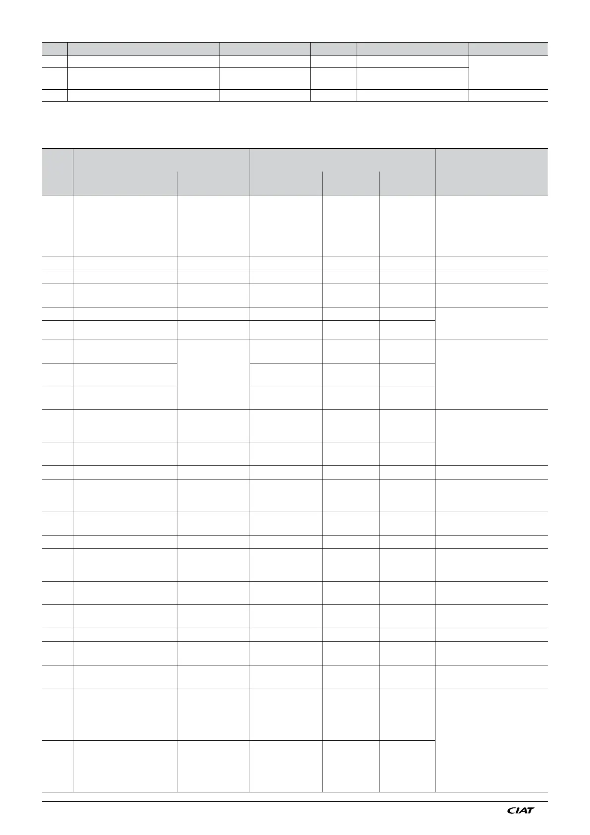
SETTINGS PARAMETERS
No.
PARAMETER NAME
PARAMETER ADJUSTMENT
Adjustment conditions
Notes
Description
Display
conditions
Adjustment
possible
By default
Adjustment
conditions
A100 LANGUAGE
French
English
German
Spanish
Dutch
Italian
French
A101 DATE
A102 TIME
A103 CONSOLE CONTROL TYPE
Local - Remote- (CMS
...)
Local
A104 Communication mode Up to V06 4800-9600-Jbus 9600 Visible up to version V06.
Creation of communication
menu from version V07.
A105 Bus number Up to V06 1-255 1
A106 RANGE WITHOUT ACTIVATION
From V07
A03 = water circuit
A07 = On/Off
0.5 to 5°C in
increments of 0.1
2
Control in place on V07, Drycooler
in On/Off control only.
A107
ACTIVATION TIME BETWEEN
STAGES
10s to 900s in
increments of 1
180
A108
DEACTIVATION TIME
BETWEEN STAGES
A109 OPERATION
A02 = 1
A03 = 1 LT water
circuit
Cooling heating
without control
Heating with control
Cooling
From V07 on drycooler only.
The heating mode allows water
from the row to be heated during
the summer.
A109.1
OUT. TEMP WARMING
OPERATING ORDER
A109 = Heating
5°C to 30°C in
increments of 1°C
10°C
A110 FAN OPERATION BALANCING A07 = On/Off or mixed Yes - No YES
A111 FREE COOLING OPERATION
A10 = NO
A2 = (1 or yes) and
A3 = 1 LT water circuit
Yes - No NO
A112 OUT. SELECTION TEMP. A111 = Yes
5 to 20 in increments
of 1
10
No effect on the operation of free
cooling. (Info for maintenance)
A113 MISTING A10 = Yes Elec.- Water Water
A113.1
MISTING CONTROL SIGNAL
FAN
A113 = Water
A10 = YES
A07 = Speed control
4 to A114 in
increments of 0.5V
10
From V07 Enables activation of
misting before the fans are at 100%
(acoustic advantage)
A114 FAN SPEED MAX THRESHOLD A07 = Speed control 2 to 10V 10
Enables the fan control to be limited
for noise reasons
A115
MINI SPEED THRESHOLD
EC FAN
A07 = Mixed 3
0 a 5 increments
of 0.1
2 From V12.3
A116 WATER CHILLER LINK Yes - No NO
A117
MIN. T DIFFERENCE TO
DEACTIVATE FREE COOLING
A111 = YES
0.5°C to 15°C in
increments of 0.5
2
Fluid temp < Out. temp + A117
Free cooling off
A118
MAX DIFFERENCE TO
ACTIVATE FREE COOLING
A111 = YES
1°C to 10°C in
increments of 0.5
4
Fluid temp > Out. temp + A118
Free cooling on
A119.1 TYPE OF COIL 1 FLUID A03 = Water
Water
Glycol 10%
Glycol 20%
Glycol 30%
Glycol 40%
Water
From V07. Allows the control
setpoint to be lowered based on the
glycol content.
Water min 5°C
10% glycol/water mix min 0°C
20% glycol/water mix min -5°C
30% glycol/water mix min -10°C
40% glycol/water mix min -15°C
A119.2 TYPE OF COIL 2 FLUID A05 = Water
Water
Glycol 10%
Glycol 20%
Glycol 30%
Glycol 40%
Water
No. Description Adjustment possible By default Display conditions Notes
A36 TOP OF CIRCUIT.2 COIL.2 SENSOR RANGE 10 to 50 b (increments of 0.1) 34 If A02 = 2 and A05 = 2 refrig. circuit
A37
BOTTOM OF CIRCUIT.2 COIL.2 SENSOR
RANGE
-1 to 10 bar (increments
of 0.1)
-0.5 If A02 = 2 and A05 = 2 refrig. circuit
A99 LOCKING No - Yes No