HEAT PUMPS - AIR CONDITIONING - REFRIGERATION - AIR HANDLING - HEAT EXCHANGE - NA 12.122 H
Water chillers and
air-water heat pumps
29
CIATCooler LP
Installation hydraulic diagram
The design of the hydraulic circuit must observe the operating conditions
(fl ows - pressure drops).
- The direction of water circulation must be observed as indicated on
the stickers on the unit.
• LP / ILP version
In this case the engineer must set up the complete hydraulic circuit
with all the components: thermal buffer tank, motorised pump group,
expansion vessel, safety, regulation, cut-off and draining valves, air
bleeder valve, etc.
- It is advisable to use fl exible hoses for connecting the piping to the
unit in order to reduce the transmission of vibrations to the building
to the greatest degree. It is mandatory to assemble hoses if the unit
is installed over shock absorbers. Optionally, a fl exible hydraulic
connections kit can be supplied.
- The pipe layouts must be set out with the lowest possible number of
bends to minimise pressure drops. The pipes must be correctly sup-
ported to prevent exerting excessive force on the unit connections.
- Before insulating the tubes and charging the system perform a pre-
liminary check to verify that there are no drops in the installation.
- The pipes must be carefully insulated to prevent leaks and condensa-
tion. Ensure that the material used is steam barrier type. Otherwise,
cover the insulation using appropriate protection.
- The water must be analysed and the circuit must be set out accord-
ing to the results. If necessary, an expert in water treatment must
be consulted (see section on corrosion behaviour).
- In installations to open circuits, if it is not possible to maintain
the water conditions within the values indicated in the corro-
sion behaviour table featured, it will be necessary to install an
exchanger that separates the unit circuit from the circuit of the
water circuit to be dealt with by using materials compatible with
these characteristics, whether stainless steel or titanium.
- Plan the anti-freeze protection for the installation when the outdoor
temperature is low: water with anti-freeze, thermal insulation of the
hydraulic circuit, electrical heaters in the hydraulic circuit, draining
from the installation when the unit does not work, etc.
- The diameters of the unit hydraulic connections can be referred to
in the next table:
CIATCooler Ø hydraulic connections
90V-STD al 100V-STD
90V-HEE al 100V-HEE
1 1/4” M
120V-STD al 180V-STD
120V-HEEal 180V-HEE
1 1/2” M
200V-STD al 360V-STD
200V-HEE al 280V-HEE
2” M
420V-STD al 960V-STD
320V-HEE al 720V-HEE
2 1/2” H
Note: optionally, a kit with cut-off and water regulation valves can
be supplied.
It is also necessary to install a fi lter in the hydraulic power
supply to the unit in order to prevent clogging of the plate
exchanger. Non-compliance with this recommendation can
cause reduced fl ow which can lead to freezing and breaking
of the exchanger.
Optionally, a kit with a stainless steel mesh fi lter (500 microns) can
be supplied.
Both at the inlet and the outlet of the unit, install thermal pressure
gauges which enable supervising the operation of the installation,
or at least plan the installation of these.
23
1
2
20
25
3
4
5
6
7
8
10
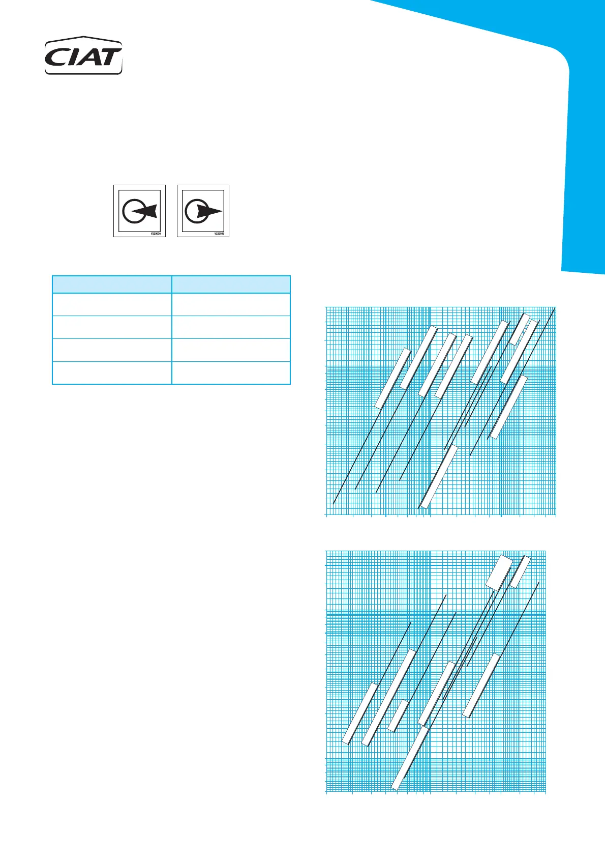
LP / ILP pressure drop (m.w.c.)
Flow (m
3
/h)
90V
-STD / 100V-STD
120V-STD / 160V
-STD
180V-ST
D /
200V-STD
240V-ST
D / 280V
-STD
320V-STD / 360V-STD
840V
-STD / 960V-STD
9
15
420V-STD /
480V
-STD
600V-STD
640V-STD / 720V-STD
4 5 6 7 8 9 10 15 20 25 30 40 50 60 70
2 3 4 405 50 607 8 9 10 15 20
1
2
3
4
5
6
0,6
7
0,7
8
0,8
10
3025
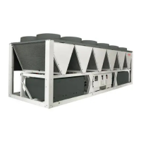
LP / ILP pressure drop (m.w.c.)
Flow ( m /h)
3
9
0,9
15
20
25
90V-HE
E / 100V-HEE
120V-HE
E /
160V-HEE / 180V-HEE
200V-HEE
240V
-HEE / 280V-HEE
320V-HE
E /
360V
-HEE
600V-HEE
640V-HE
E / 720V-HEE
420V
-HEE
480V
-HEE
6